Moving-magnet transfer platform

a technology of moving magnets and moving plates, applied in the direction of control systems, dynamo-electric machines, structural associations, etc., can solve the problems of affecting the efficiency of heat dissipation, and generating a large amount of heat, so as to simplify the heat dissipation mechanism and enhance the heat dissipation efficiency. , the effect of simplifying the driving par

Active Publication Date: 2018-09-06
DELTA ELECTRONICS INC
View PDF0 Cites 3 Cited by
  • Summary
  • Abstract
  • Description
  • Claims
  • Application Information

AI Technical Summary

Benefits of technology

[0009]An object of the present invention provides a moving-magnet transfer platform with a simplified heat dissipating mechanism, enhanced heat dissipating efficiency, cost-effectiveness, simplified driving part and stable working status.

Problems solved by technology

When the electric power flows through the coils of the coil assembly, a great amount of heat is generated.
Under this circumstance, the moving-magnet transfer platform is complicated and the heat dissipating efficacy is impaired.
The use of the drag chain increases the fabricating cost of the moving-magnet transfer platform.
Since the material cost of the permanent magnets is high, the fabricating cost of the conventional moving-magnet transfer platform is increased.
As mentioned above, the driving part of the conventional moving-magnet transfer platform issues the driving power.
Consequently, the circuitry of the driving part is more complicated.
Due to the current fluctuation, the working status of the driving part is unstable.

Method used


Image

  • Moving-magnet transfer platform
  • Moving-magnet transfer platform
  • Moving-magnet transfer platform

Examples


first embodiment

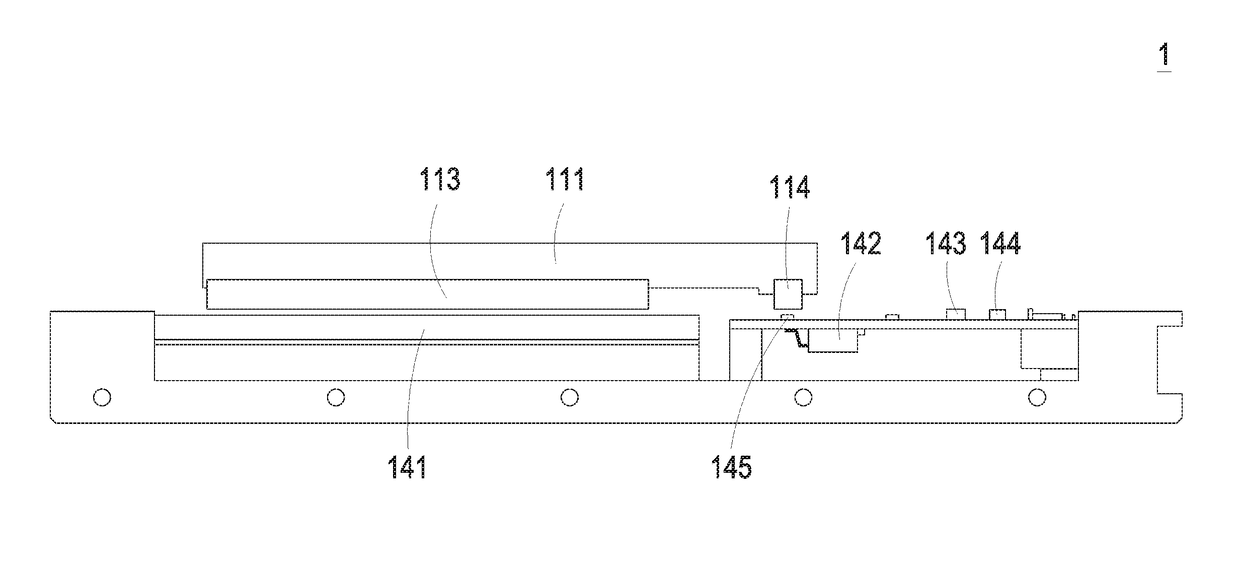
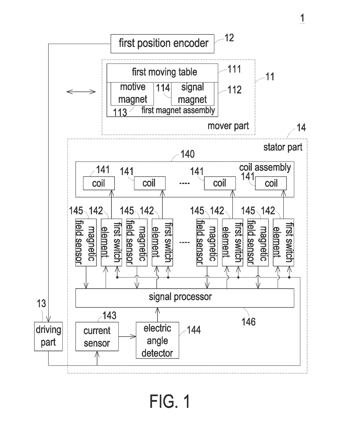
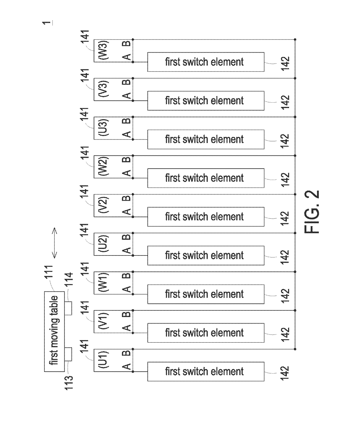
[0023]FIG. 1 is a schematic block diagram illustrating the architecture of a moving-magnet transfer platform according to the present invention. FIG. 2 is a schematic block diagram illustrating the relationships between the coils and the first switch elements of the moving-magnet transfer platform as shown in FIG. 1. FIG. 3 is a schematic cross-sectional view illustrating a portion of the moving-magnet transfer platform as shown in FIG. 1. An example of the moving-magnet transfer platform is a linear motor. In this embodiment, the moving-magnet transfer platform 1 comprises a mover part 11, a driving part 13 and a stator part 14. The mover part 11 is disposed over the stator part 14 and movable relative to the stator part 14. The mover part 11 comprises at least one moving table and at least one magnet assembly. In this embodiment, the mover part 11 comprises a first moving table 111 and a first magnet assembly 112. The first moving table 111 is moved over the stator part 14 in a re...

second embodiment

[0035]FIG. 4 is a schematic block diagram illustrating the architecture of a moving-magnet transfer platform according to the present invention. In comparison with FIG. 1, the mover part 11 of the moving-magnet transfer platform 1 further comprises a second moving table 41 and a second magnet assembly 42. Moreover, the stator part 14 of the moving-magnet transfer platform 1 further comprises another magnetic field sensor assembly with plural magnetic field sensors 44. Namely, the stator part 14 of the moving-magnet transfer platform 1 comprises a first magnetic field sensor assembly with plural first magnetic field sensors 145 and a second magnetic field sensor assembly with plural second magnetic field sensors 44. The second moving table 41 is connected with the first moving table 111 in series. Moreover, the second moving table 41 is moved over the stator part 14 in a reciprocating manner. The second magnet assembly 42 is disposed on a bottom surface of the second moving table 41....

third embodiment

[0040]FIG. 7 is a schematic block diagram illustrating the architecture of a moving-magnet transfer platform according to the present invention. As shown in FIG. 7, the moving-magnet transfer platform 7 comprises a mover part 71, a driving part 73 and a stator part 74. The structures and operations of the mover part 71 and the driving part 73 are similar to those of FIG. 1, and are not redundantly described herein. In comparison with FIG. 1, the plural first magnetic field sensors 145 of this embodiment are analog magnetic field sensors. Moreover, the stator part 74 of the moving-magnet transfer platform 7 further comprises an analog-to-digital converter 72 and a first position encoder 75. The analog-to-digital converter 72 is connected between the plural first magnetic field sensors 145 and the signal processor 146. The analog-to-digital converter 72 is used for converting the analog sensing results of the first magnetic field sensors 145 into digital sensing results and providing ...


PUM


Abstract

A moving-magnet transfer platform includes a mover part, a driving part and a stator part. The mover part includes a moving table and a magnet assembly. The stator part includes plural coils, plural switch elements, a current sensor, an electric angle detector, plural magnetic field sensors and a signal processor. The plural switch elements are connected between the driving part and the corresponding coils. When the magnet assembly is moved to a position of the corresponding coil, a magnetic field change is detected by the corresponding magnetic field sensor. The signal processor is used for controlling operations of the plural switch elements. When the magnet assembly is moved to the position of the corresponding coil, the corresponding switch element is turned on under control of the signal processor, so that the moving table is moved with the magnet assembly.

Description

FIELD OF THE INVENTION[0001]The present invention relates to a transfer platform, and more particularly to a moving-magnet transfer platform.BACKGROUND OF THE INVENTION[0002]With increasing development of science and technology, transfer platforms are widely applied to various fields. For example, a transfer platform is equipped with a linear motor to carry and transfer objects automatically. Moreover, the conventional transfer platform further comprises a ball screw. The cooperation of the ball screw and the motor is used for controlling the moved position of the transfer platform. Nowadays, the demands on the performance of the transfer platform are gradually increased. For example, the transfer platform needs to have many benefits such as high speed, low noise and high positioning precision. For achieving these benefits, a moving-magnet transfer platform was introduced into the market. Consequently, the mechanical transfer platform including the motor and the ball screw is replac...

Claims


Application Information

Patent Timeline
Patent Type & Authority Applications(United States)
IPC IPC(8): H02K41/03H02K11/215H02K11/33H02K11/27H02P25/064
CPCH02K41/031H02K11/215H02K11/33H02K11/27H02P25/064H02K33/18
Inventor TSAI, CHING-HSIUNGCHUNG, CHI-WENLU, CHIEH-HUANG
Owner DELTA ELECTRONICS INC
Why Eureka
Try Eureka