Solar field canvas

Inactive Publication Date: 2012-12-06
ABRAMOWITZ YOSEF
View PDF4 Cites 2 Cited by
  • Summary
  • Abstract
  • Description
  • Claims
  • Application Information

AI Technical Summary

Benefits of technology

[0006]Generally, all types of solar fields must have very good sky footage. Sky footage (skf) is the total exposure of any area being considered for

Problems solved by technology

Because a single solar panel can only produce a limited a

Method used


Image

  • Solar field canvas
  • Solar field canvas
  • Solar field canvas

Examples


Embodiment Construction

[0039]The principles and operation of a innovative solar field according to the present invention may be better understood with reference to the drawings and the accompanying description.

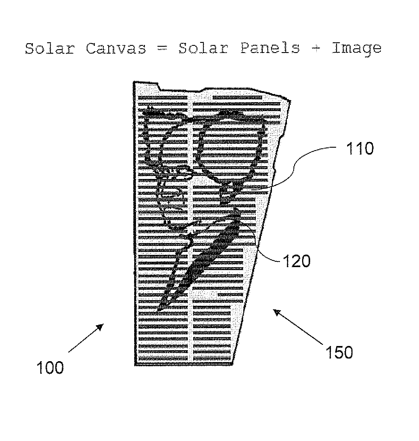
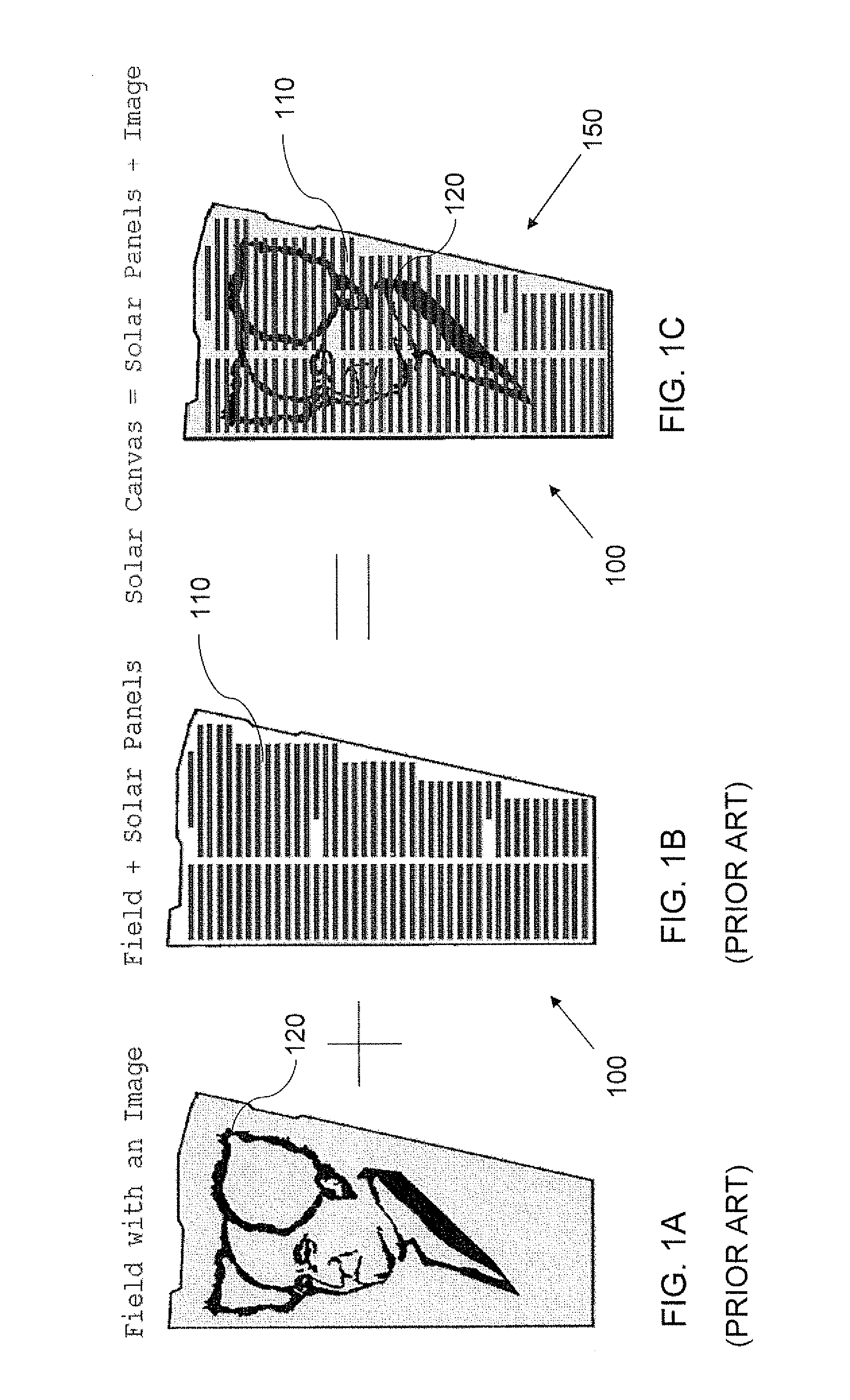
[0040]Referring now to the drawings, FIG. 1 illustrate the basic concept of the invention whereby there is produced a landscaped image 120 (FIG. 1A) on the ground and a solar field 100 (FIG. 1B) including rows of solar panels 110 which together are viewed aerially to produce the visual effect termed herein as a ‘solar canvas’150 (FIG. 1C).

[0041]A number of options are envisioned: Low-tech physical mediums in collaboration with the panels, high-tech / digital images and designer formations.

[0042]Low-Tech Medium

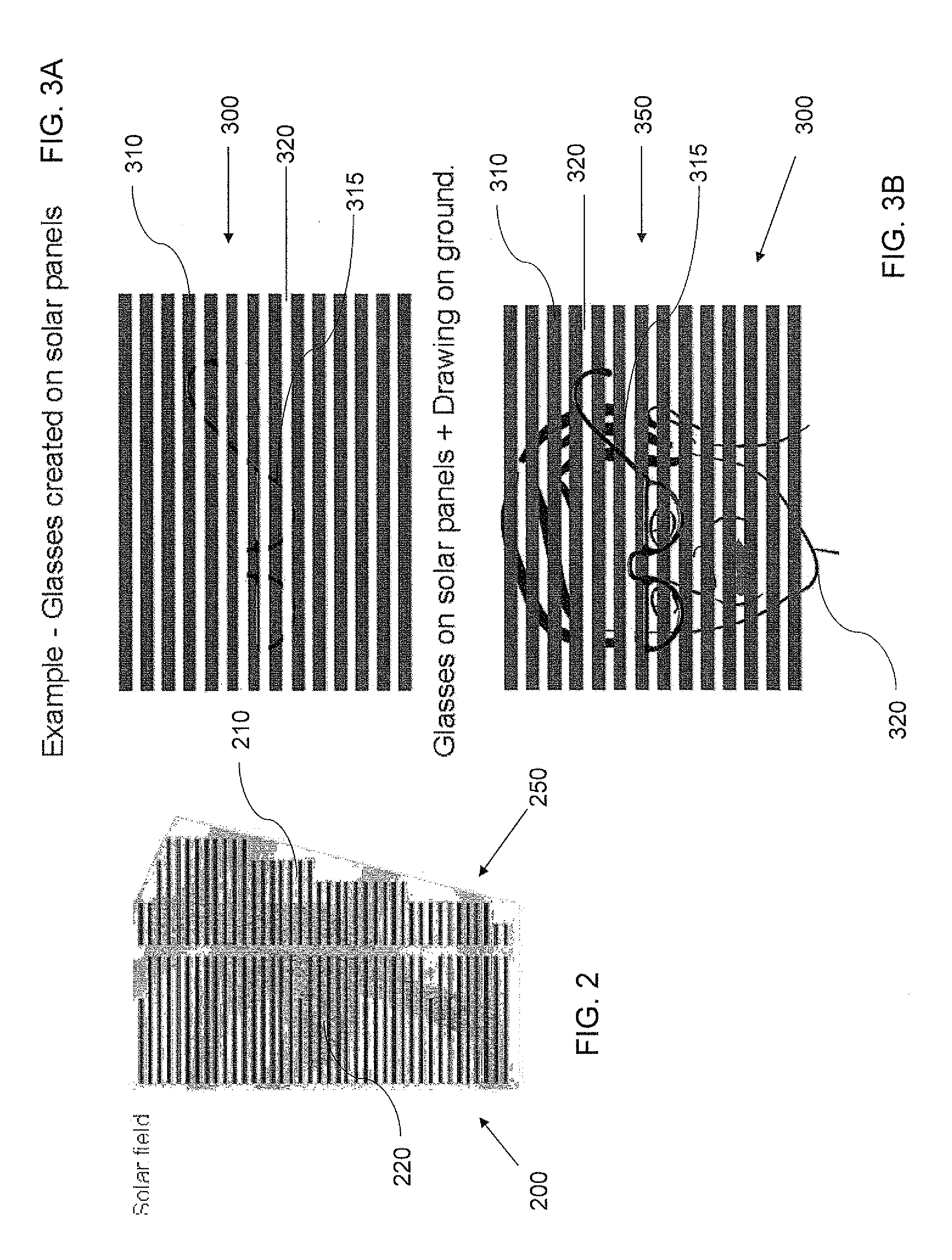
[0043]FIG. 2 is an exemplary embodiment of a solar field 200 combined with a landscaped image 220. Referring to the embodiment depicted in FIG. 2, the setting of the solar field presents itself as a variable background (landscaped earth) with a substantially constant medium (the solar panels).

[00...


PUM


Abstract

A solar field made up of a plurality of mutually adjacent solar panels and a substantially horizontal visual display associated aerially with at least a portion of the solar panels. The field may include landscaping which forms at least a portion of the display. The solar panels may include differently colored solar cells arranged to form at least a portion of the display. The field may include a plurality of light emitting elements, coupled to at least a portion of the solar panels and controlled to selectively display a visual image.

Description

[0001]This patent application claims the benefit of U.S. Provisional Patent Application No. 61 / 493,468, filed Jun. 5, 2011FIELD AND BACKGROUND OF THE INVENTION[0002]The present invention relates to a solar panel field and, more particularly, to a system and method for providing a system of solar panels in a solar panel field having a distinctive configuration and / or adaptation to provide a particular visual representation.[0003]A photovoltaic module or photovoltaic panel, is a packaged interconnected assembly of solar cells, also known as photovoltaic cells. This type of solar panel can be used as a component of a larger photovoltaic system to generate and supply electricity in commercial and residential applications. Because a single solar panel can only produce a limited amount of power, many installations contain several panels. Solar fields (including any solar energy-gathering technology, not limited to photovoltaic cells as discussed below) are large open areas which have been...

Claims


Application Information

Patent Timeline
IPC IPC(8): H01L31/048G06Q30/00
CPCY02E10/50H01L31/02G09F23/00G09F27/007F24J2/00G09F2013/222F24S20/00H02S10/00Y02E10/40
Inventor ABRAMOWITZ, YOSEFLAVIE, DANNY
Owner ABRAMOWITZ YOSEF
Why Eureka
Try Eureka