Interlocking masonry wall block

a masonry wall and interlocking technology, applied in the field of masonry blocks, can solve the problems of increased installation costs, increased installation costs, and insufficient friction in many retaining wall applications, and achieve the effect of uniform amount of setback, constant pitch and relatively constant pitch

Inactive Publication Date: 2005-05-05
BEND INDS
View PDF28 Cites 25 Cited by
  • Summary
  • Abstract
  • Description
  • Claims
  • Application Information

AI Technical Summary

Benefits of technology

[0018] One advantage of the present interlocking masonry wall block is that the thickness of the integral projections is not related to the desired amount of setback for each course of blocks. A retaining wall application requiring a half-inch setback per course can have projections that are one or two inches thick. These thicker projections are more structurally sound and not prone to chipping and cracking. The block can be relatively short in height to produce a block that is light weight and easy to handle.
[0027] A still further advantage of the present interlocking masonry wall block is its reduced weight. The open core and hand hold designs reduce the weight of the block so that they are easier to handle during manufacture, shipping and construction. The open core and hand hold designs also reduces material costs, which can be passed on to the consumer.

Problems solved by technology

While the friction between the relatively rough surfaces of stacked blocks can help keep the wall together, this friction is not sufficient in many retaining wall applications.
Unfortunately, such retaining walls are prone to cracking due to settling, frost, water buildup behind the wall and earthquakes, as well as the normal use of the wall by people and animals that walk, stand, lean or sit on the wall.
A significant problem with these block designs is the expense of the extra components and increased installation costs.
These designs can also suffer from unsightly cracks that tend to form in these types of walls.
One problem with conventional interlocking masonry wall blocks is that the thickness of the integral projection is directly related to the amount of setback desired for each course of blocks.
Yet, thin projections are structurally weak and prone to chipping and cracking.
While the height of the block can be increased to increase the thickness of its setback, this results in a heavier block that is more difficult to handle.
In addition, tall blocks also do not lend themselves to landscaping gradually sloping terrain.
This produces an unsightly wall and results in a waste of material.
Another problem with conventional interlocking masonry wall blocks is that the integral projection is located along the rear or front edge of the block.
Yet, these relatively thin and weak projections are located where they are easily damaged if dropped, improperly stacked or otherwise mishandled.
In addition, rear projections are in direct contact with the wetness and acidity of the earth during use, which can cause the projection to deteriorate, weaken and fail over time.
Front projections extend upwardly and can collect water between them and the upper course of blocks, which can freeze and crack the projection.
A further problem with conventional interlocking masonry wall blocks is that the integral projections are relatively short in height to reduce the possibility of chipping and cracking.
Although the short projections may be less likely to crack, they do not provide a sufficiently tall abutment to easily and consistently align the block over a lower course of blocks.
During construction of a wall, workers have a tendency to leave a gap between the projection and the lower course of blocks or allow the projection to ride-up onto the upper surface of the lower block.
These misalignments are not easily detected given the thinness of the projection and its relatively small height.
This is especially so for blocks with rear projections that extend down from the lower surface of the block, because the workers are not able to easily see that the blocks are properly aligned.
Misalignments can be even more difficult to notice in construction settings where dirt, gravel and other debris are present, and may compact against the setback projection or get on the upper or lower surfaces of the blocks.
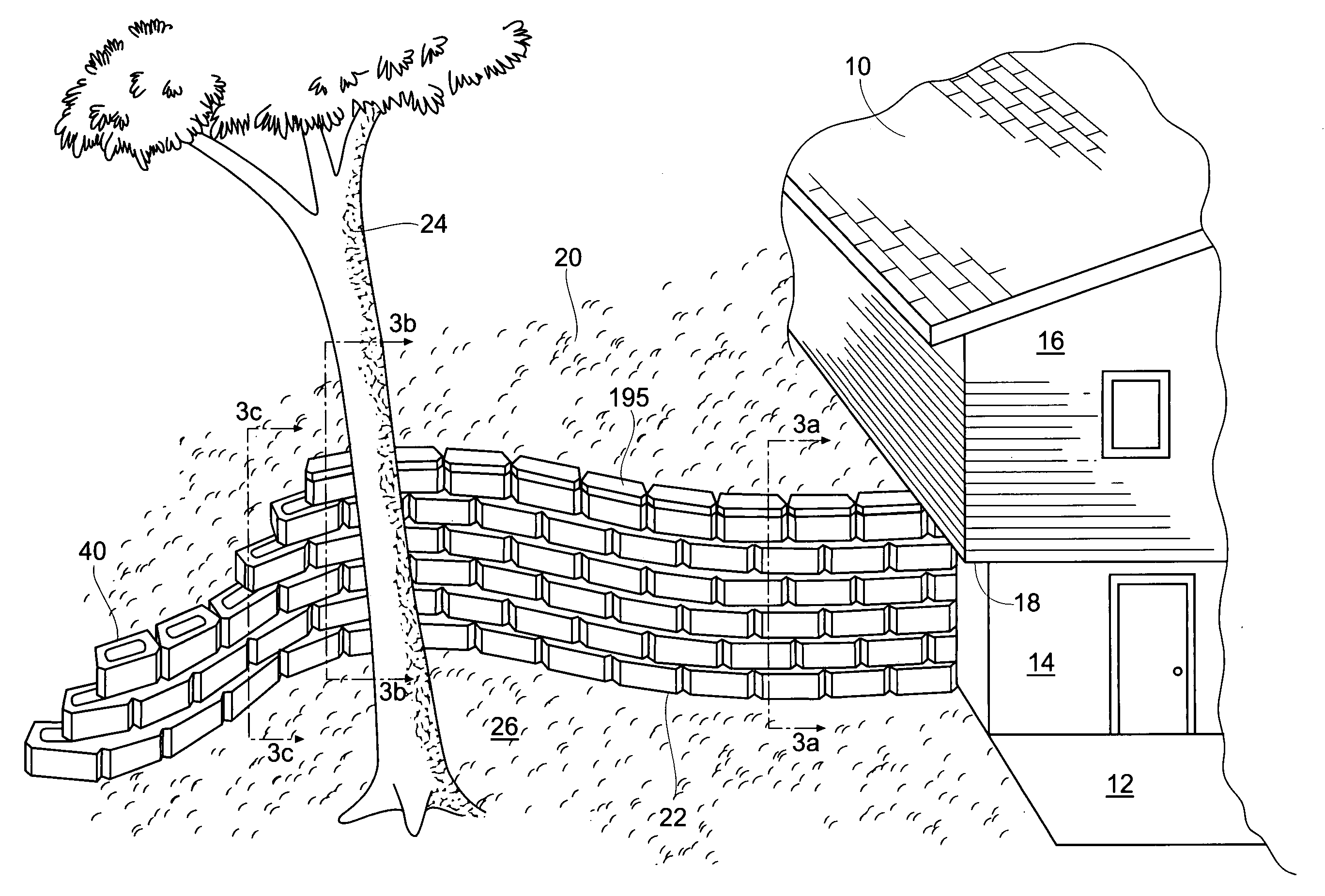
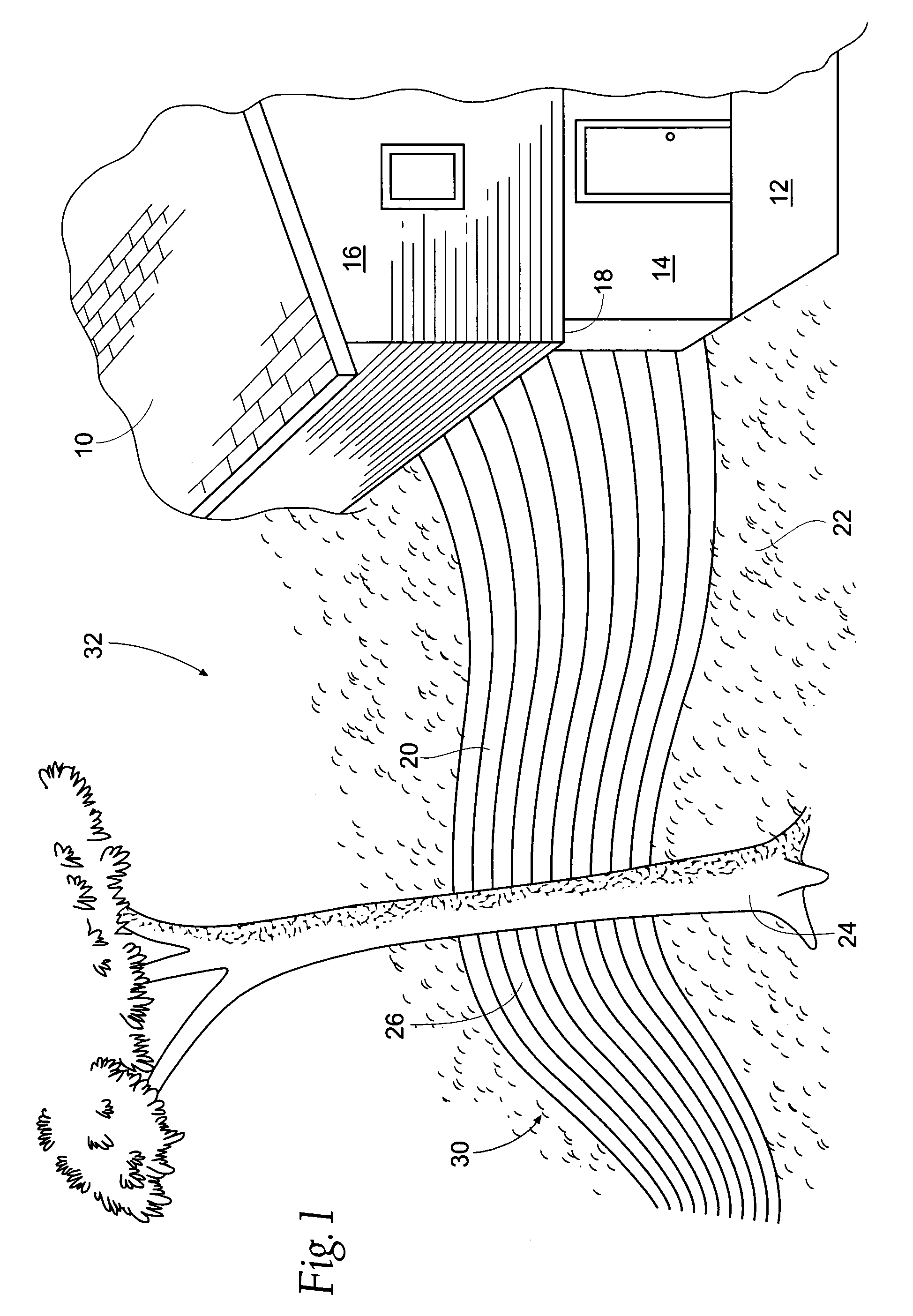
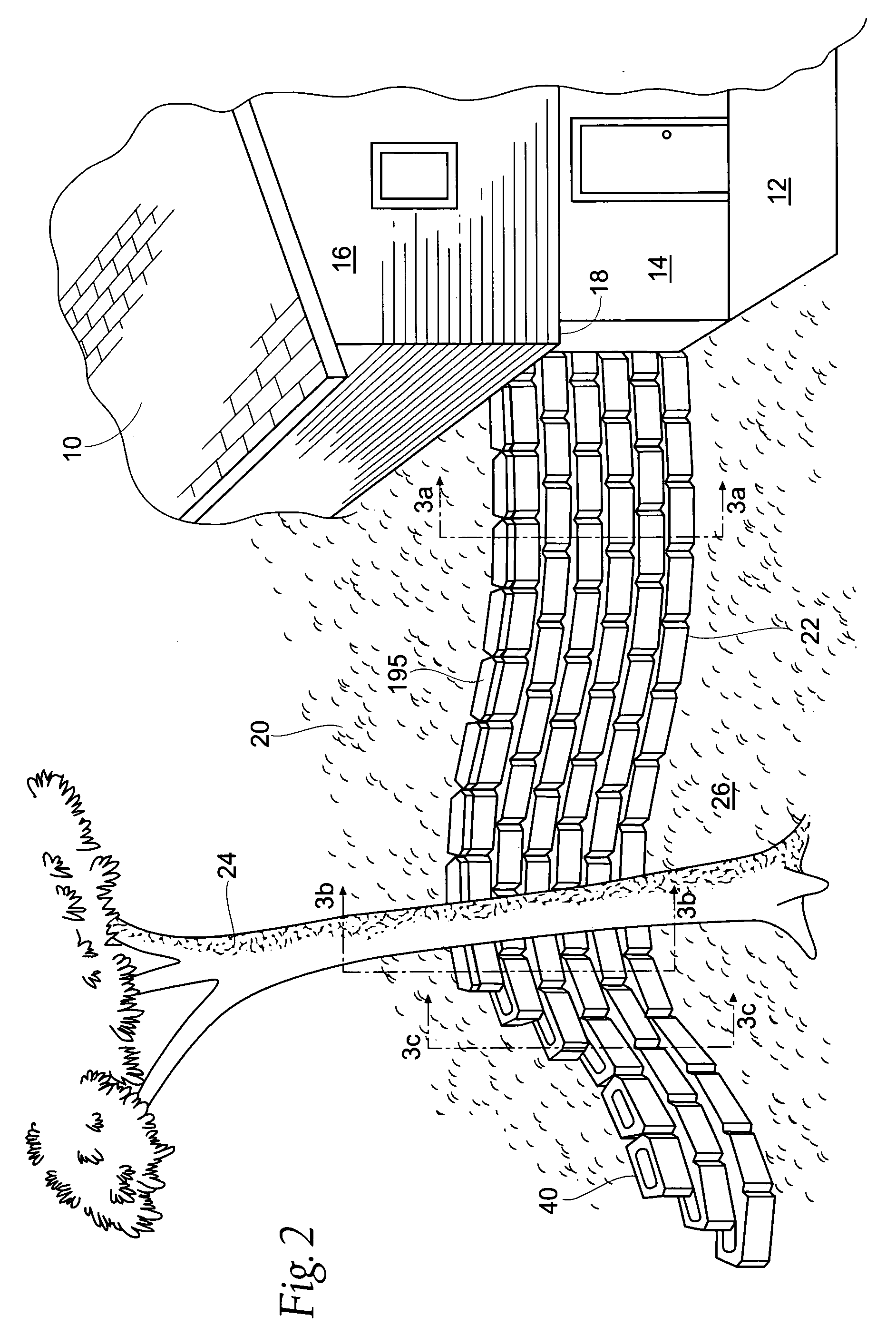
A still further problem with conventional interlocking masonry wall blocks is that they have limited ability to produce serpentine walls with straight, concave and convex portions.
If a curve is possible, the radius of the curve is constant, so that a true serpentine wall with curves that gradually increase or decrease in radius are not possible.
These limitations of conventional block designs prevent the wall from being integrated into the natural contours of the landscape and thus impede the aesthetic value of the wall.
A still further problem with conventional interlocking masonry wall blocks is that the integral projections do not ensure an even amount of setback for straight and curved portions of the wall.
This increasing setback and pitch occurs even though a retaining wall may need to be stronger and require more setback in straight portions of the wall than in curved portions.
A still further problem with conventional interlocking masonry wall blocks is that the blocks require a fixed amount of lateral offset to the right or left of the lower blocks on which they rest.
Yet, obstructions at the location where the wall is to be built or the addition of drain pipes in the wall do not always permit each block to be offset a constant amount throughout the entire wall.
Yet, many interlocking block designs do not allow sufficient flexibility to offset the blocks as needed to accommodate various obstacles or drain pipes.
This inflexibility can complicate construction or renders the block unusable for some retaining wall applications.
A still further problem with conventional interlocking masonry wall blocks is that the integral projection does not provide sufficient resistance to lateral side-to-side movement of the block.
However, should one block in a given course shift or move out of abutting alignment with one of its adjacent blocks, then each of the blocks in that row would be susceptible to shifting as well.
Moreover, the blocks that form an end of the wall are not restrained from lateral movement away from its sole adjacent block and could be knocked off the wall altogether.
A still further problem with conventional interlocking masonry wall blocks is that several different block shapes must be combined to form the straight and curved sections of a serpentine wall.
The need for multiple block designs result in increased manufacturing, inventory, shipping and construction costs.
The multiple block designs also result in more complicated serpentine wall designs that are not easily integrated to the shape of a specific and unique landscape setting.
A still further problem with conventional interlocking masonry wall blocks is that they are heavy and difficult to handle.
The excessive weight is compounded by the fact that the block must be tall enough to provide a setback projection or flange that is sufficiently thick to withstand cracking and chipping during transport, construction and use.

Method used


Image

  • Interlocking masonry wall block
  • Interlocking masonry wall block
  • Interlocking masonry wall block

Examples


Embodiment Construction

[0080] While this invention is susceptible of embodiments in many different forms, the drawings show and the specification describes in detail several preferred embodiments of the invention. It should be understood that the drawings and specification are to be considered an exemplification of the principles of these inventions. They are not intended to limit the broad aspects of the inventive block designs to the embodiments illustrated.

[0081]FIG. 1 shows a house 10 with a walkout basement leading to a patio 12 constructed in the backyard of the house. The house 10 has a concrete foundation 14 which transitions to brick 16 along a sill 18 at the top of the foundation. The house is constructed into a hill 20 that levels off to a particular ground level 22 in the backyard of the house. The hill 20 and its terrain 30 and natural plant life 24 form a unique landscape setting 32 around the house 10.

[0082]FIGS. 2-16 pertain to a first interlocking masonry block design that is generally ...


PUM


Abstract

The present invention relates to an interlocking masonry wall block having two spaced lugs or projections and a cooperating recess or channel that enable like-shaped blocks to be stacked in a staggered relation to form straight and serpentine walls that are particularly suited for landscaping applications. In one embodiment, the lugs are located proximal the sides of the block and extend from an upper surface of the block. The channel is formed in a lower surface of the block. In another embodiment, the lugs are located at the rear corners of the block and extend below the lower surface of the block. The recess is formed in the rear end of the block between the lugs. Like-shaped blocks are stacked in a staggered relation so that each block is stacked atop two immediately lower blocks. In each embodiment, the lugs and their cooperating channel or recess define a setback dimension.

Description

RELATED APPLICATIONS [0001] This application is a divisional of co-pending U.S. application Ser. No. 09 / 940,562, filed Aug. 28, 2001, entitled “Interlocking Masonry Wall Block” which claims the benefit of provisional U.S. Application Ser. No. 60,228,517, filed Aug. 28, 2000, and which is a continuation-in-part of U.S. application Ser. No. 09 / 928,125, filed Aug. 10, 2001, entitled “Interlocking Masonry Wall Block,” now abandoned, which claims the benefit of provisional U.S. Application No. 60 / 224,471, filed Aug. 10, 2000.TECHNICAL FIELD OF THE INVENTION [0002] This invention relates to a masonry block for stacking on other like-shaped blocks in a staggered, interlocking and offset manner to form a gravity-type retaining wall that is particularly suited for integrating into a variety of landscape settings. BACKGROUND OF THE INVENTION [0003] A variety of masonry block designs have been developed for building gravity-type retaining walls that depend on the weight of the blocks for their...

Claims


Application Information

Patent Timeline
Patent Type & Authority Applications(United States)
IPC IPC(8): E02D29/02E04B2/02E04C1/39
CPCE02D29/025E04C1/395E04B2002/0223
Inventor WHITSON, ROBERT L.
Owner BEND INDS
Why Eureka
Try Eureka