

Tower Construction and a Method for Erecting the Tower Construction
- Summary
- Abstract
- Description
- Claims
- Application Information
AI Technical Summary
Benefits of technology
Problems solved by technology
Method used
Image

Examples
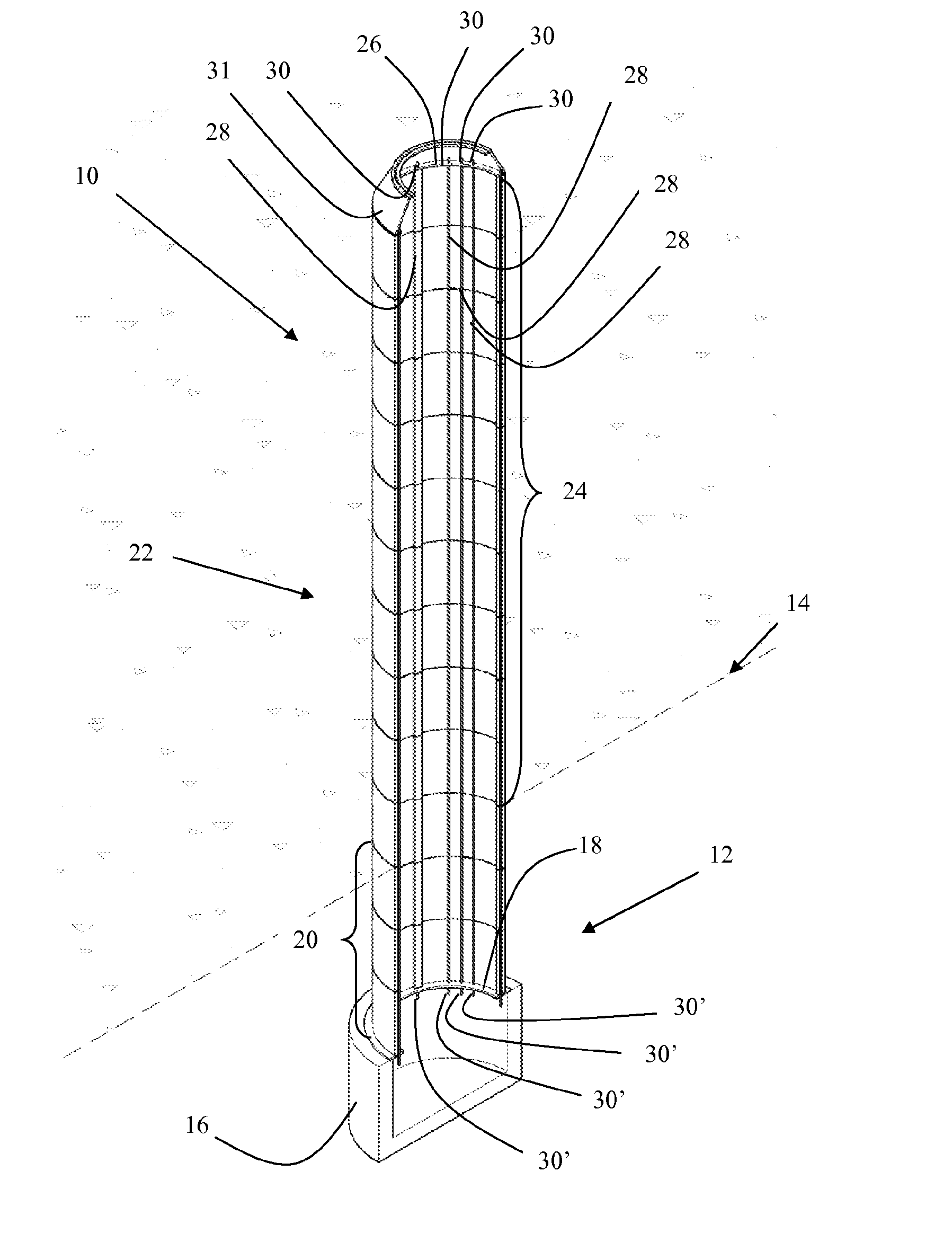
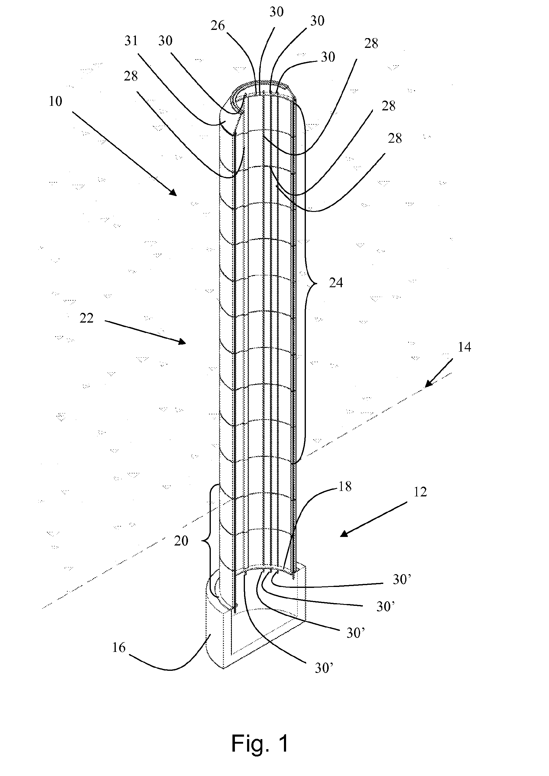
first embodiment
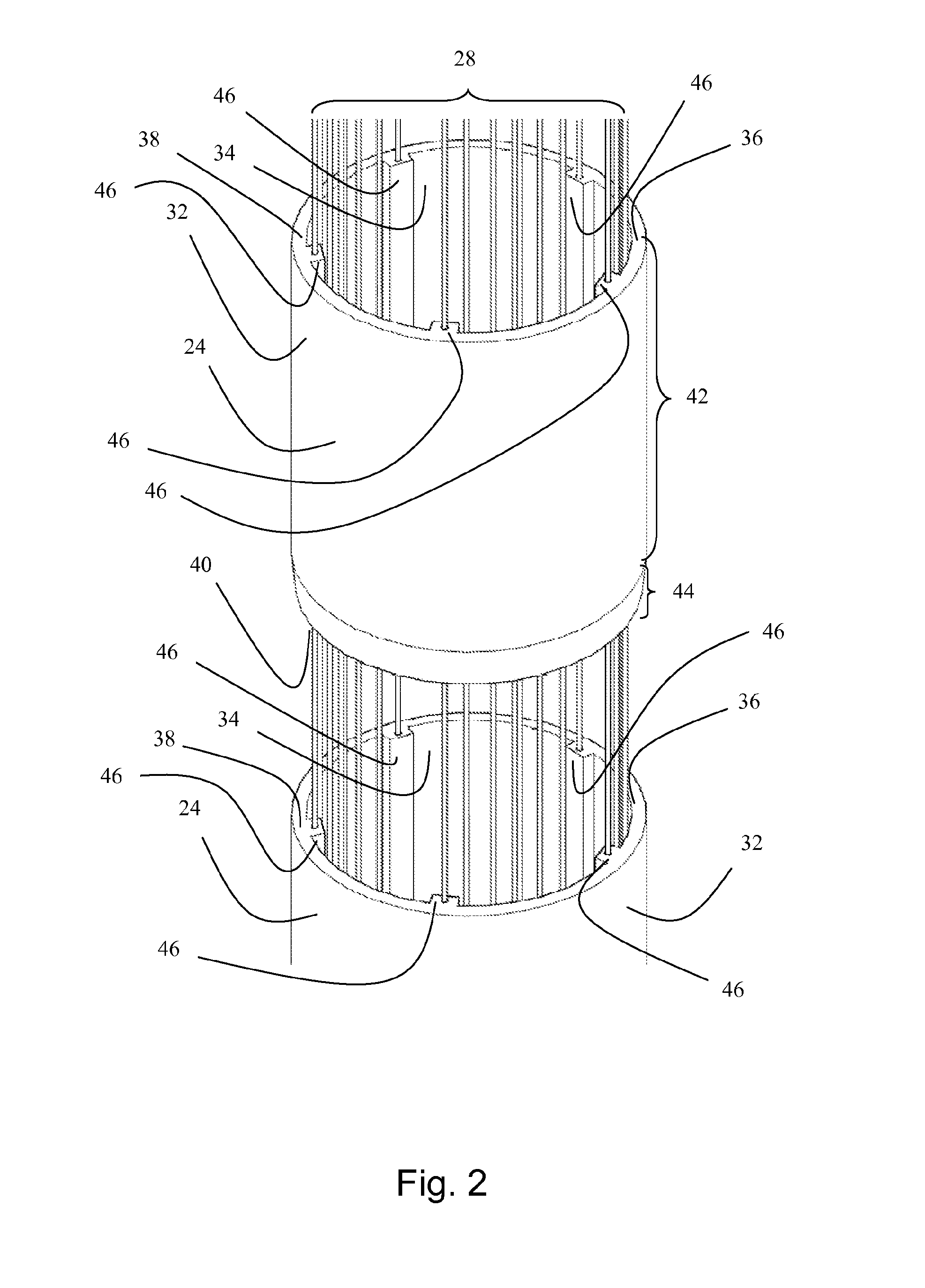
[0162]FIG. 2 shows an exploded view two tower elements of the tower construction according to FIG. 1,
[0163]FIG. 3 shows a cross sectional side view of a foundation of the tower construction according to FIG. 1,
[0164]FIG. 4 shows a cross sectional side view of a foundation of the tower construction according to an alternative embodiment,
[0165]FIG. 5 shows a cross sectional side view of the upper part of the tower construction according to FIG. 1,
[0166]FIG. 6a shows a cross section of a first embodiment of a tower element,
[0167]FIG. 6b shows a section view of a tower element along A-A of FIG. 6a,
second embodiment
[0168]FIG. 7a shows a cross section of a tower element,
[0169]FIG. 7b shows a section view of a tower element along A-A of FIG. 7a,
third embodiment
[0170]FIG. 8 shows an isometric section view of a tower element,
[0171]FIG. 9 shows a plan view of a tower element according to FIG. 8,
PUM
 Abstract
Description
Claims
Application Information