Acceleration measuring apparatus

a measuring apparatus and acceleration technology, applied in the direction of speed/acceleration/shock measurement, measurement devices, instruments, etc., can solve the problems of weak and low frequency acceleration detection, short life of the photodiode, and inability to eliminate noise, so as to achieve easy detection, suppress the influence of noise and temperature characteristics, and high accuracy

Inactive Publication Date: 2012-12-13
NIHON DEMPA KOGYO CO LTD
View PDF15 Cites 12 Cited by
  • Summary
  • Abstract
  • Description
  • Claims
  • Application Information

AI Technical Summary

Benefits of technology

[0012]The present invention was created in light of the above-described background, and an objective thereof is to provide an acceleration measuring apparatus that can easily detect acceleration with high accuracy.
[0028]The present invention captures the displacement when the pendulum member is displaced from a reference position upon swinging due to acceleration as a change in the oscillating frequency of the piezoelectric plate via a change in a capacitance between the movable electrode of the pendulum member and the fixed electrode that opposes the movable electrode. Therefore, the acceleration can be easily detected with high accuracy. Further, by forming a variable capacitance on both sides relative to the direction in which the pendulum swings, a differential method can be applied when measuring a change in the oscillating frequency. Thus, the influence of noise and temperature characteristics can be suppressed, and the acceleration can be detected with even higher accuracy.

Problems solved by technology

In order to measure an earthquake or the like, one important issue is detecting weak and low frequency acceleration.
However, an optical-type pendulum position detector presents problems in that it has a complex structure and the life of the photodiode is short.
However, the influence of noise cannot be eliminated, and thus it is difficult to detect the acceleration with high accuracy.

Method used


Image

  • Acceleration measuring apparatus
  • Acceleration measuring apparatus
  • Acceleration measuring apparatus

Examples


Embodiment Construction

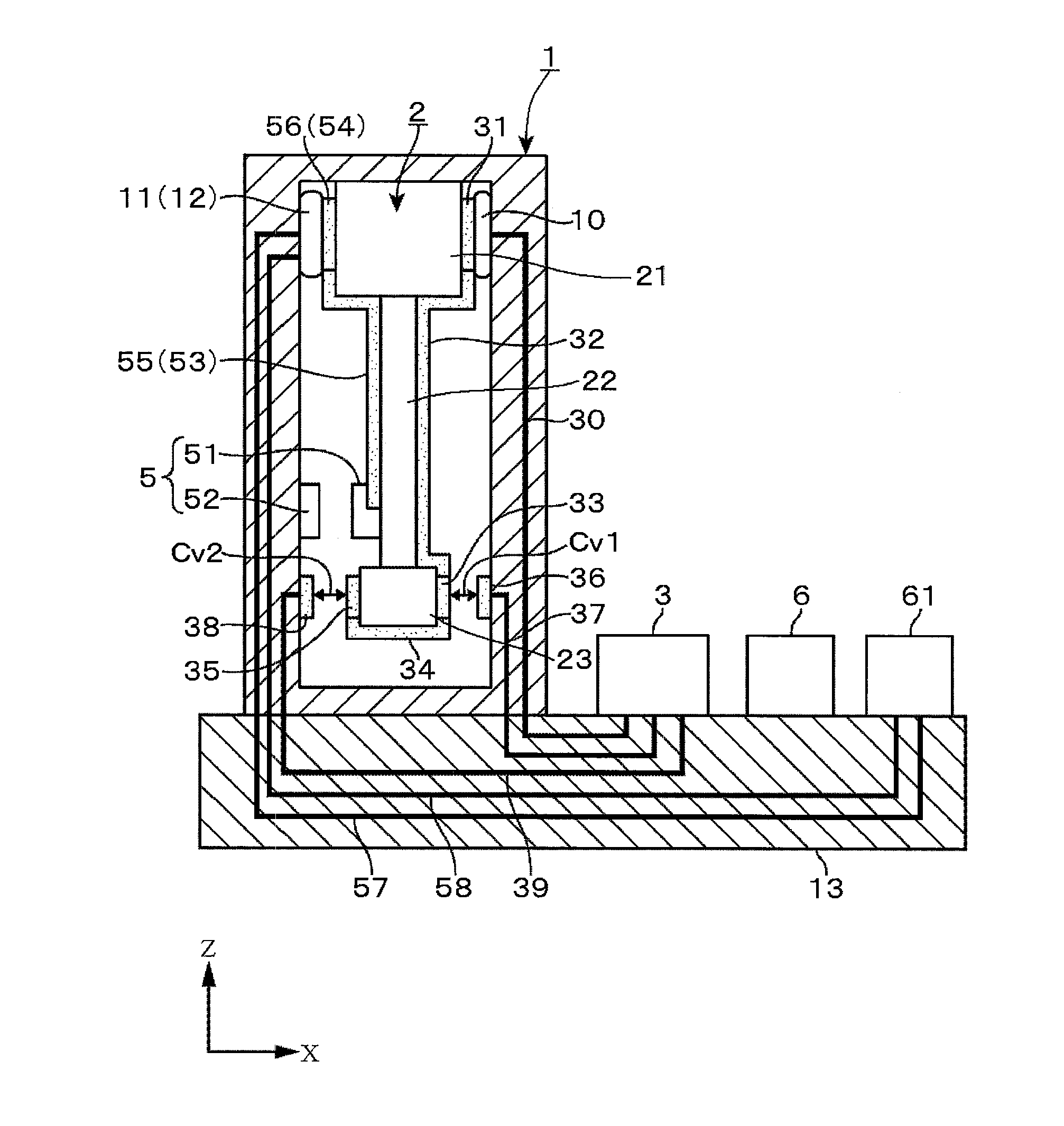
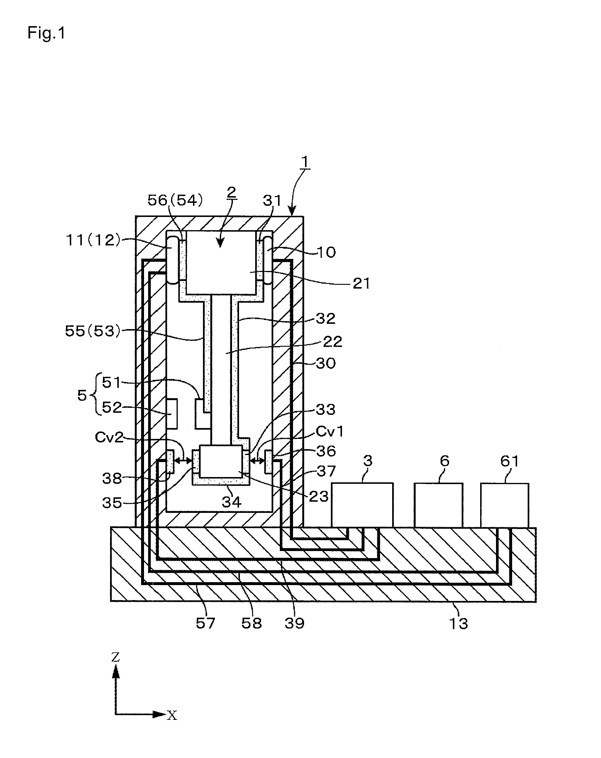
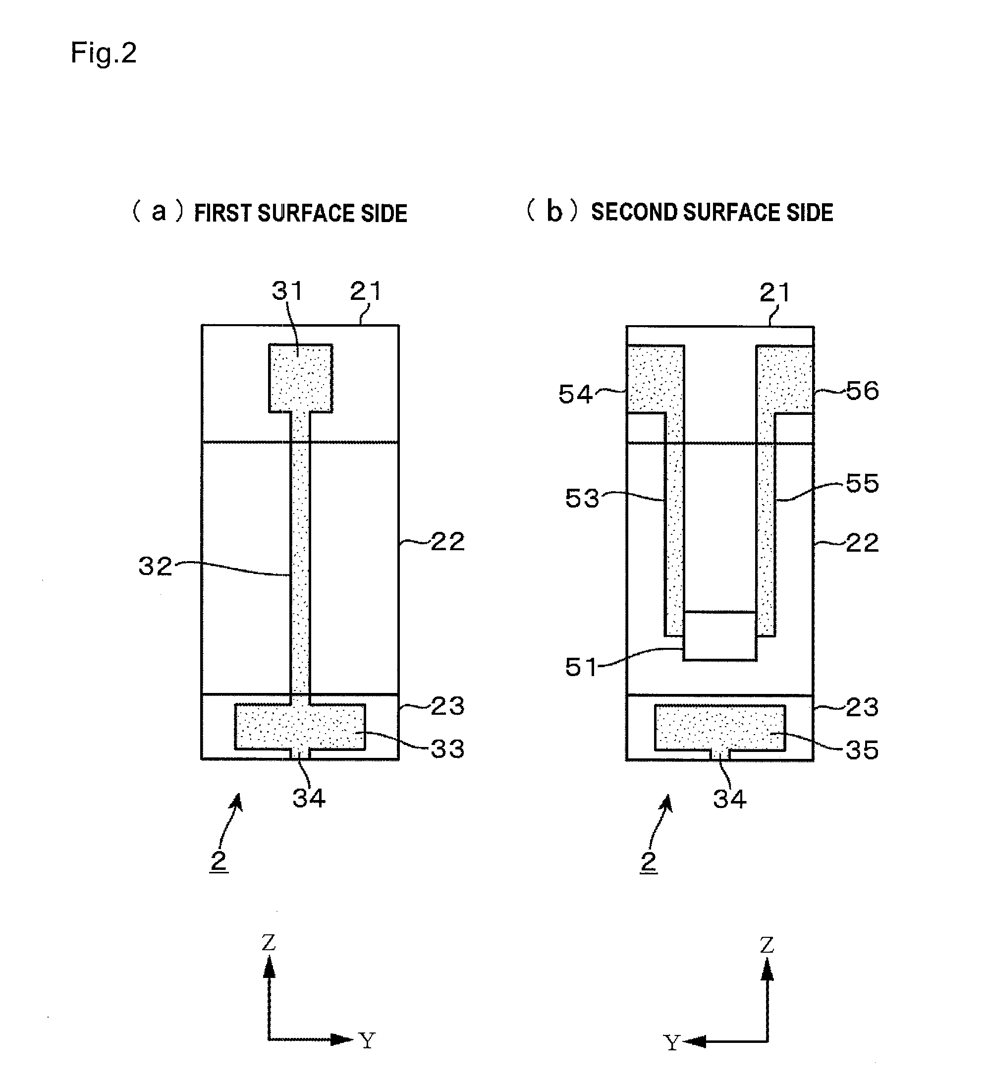
[0037]A servo-type acceleration measuring apparatus according to an embodiment of the present invention will now be explained. The servo-type acceleration measuring apparatus of this embodiment is mainly constituted by a pendulum member that is a target of position control, a pendulum position detecting unit that detects a positional displacement of the pendulum based on a change in oscillating frequency and outputs an electrical signal of the positional displacement data, a regulating unit that controls the output of an actuator so that the pendulum is maintained in a stationary state based on the positional displacement data received from the pendulum position detecting unit, an actuator that exerts a force on the pendulum, and, for example, a data processing unit that calculates an acceleration of an inertial force from the amount of the driving electric power of the actuator. FIG. 1 is a view illustrating the servo-type acceleration measuring apparatus according to the present e...


PUM


Abstract

An acceleration measuring apparatus that can easily detect acceleration with high accuracy is provided. In the apparatus, positional displacement of a swingable pendulum member is detected, feedback control is performed to maintain the pendulum member in a stationary state using an actuator, and acceleration is measured by measuring the output of the actuator at this time. A movable electrode is provided to the pendulum member, and a loop is formed in which a fixed electrode provided to oppose the movable electrode, and an oscillating circuit, a crystal unit, and the movable electrode are electrically connected in series. By measuring an oscillating frequency of the oscillating circuit at this time, a change in the size of a variable capacitance formed between the movable electrode and the fixed electrode is detected, and thereby the positional displacement of the pendulum member is detected.

Description

CROSS-REFERENCE TO RELATED APPLICATION[0001]This application claims the priority benefit of Japanese application serial no. 2011-127644, filed Jun. 7, 2011. The entirety of the above-mentioned patent applications is hereby incorporated by reference herein and made a part of specification.BACKGROUND OF THE INVENTION[0002]1. Field of the Invention[0003]The present invention relates to a technology for detecting acceleration based on an oscillating frequency using a piezoelectric plate such as a crystal plate.[0004]2. Description of Related Art[0005]In order to measure an earthquake or the like, one important issue is detecting weak and low frequency acceleration. It is desirable to measure with high accuracy using a structure that is as simple as possible when carrying out this kind of measurement. As a sensor for detecting weak and low frequency acceleration, a servo-type acceleration measuring apparatus is often used.[0006]In general, a servo-type acceleration measuring apparatus is...

Claims


Application Information

Patent Timeline
Patent Type & Authority Applications(United States)
IPC IPC(8): G01P15/09
CPCG01P2015/0817G01P15/125G01P15/097
Inventor KOYAMA, MITSUAKIMUTOH, TAKERUIWAI, HIROKIICHIKAWA, RYOICHI
Owner NIHON DEMPA KOGYO CO LTD
Why Eureka
Try Eureka