
Gripper for continuous elongated members, vehicle movable along a continuous elongated member, and method of advancing the vehicle

Active Publication Date: 2012-12-13
SAIPEM SPA
View PDF14 Cites 0 Cited by
  • Summary
  • Abstract
  • Description
  • Claims
  • Application Information

AI Technical Summary

Benefits of technology

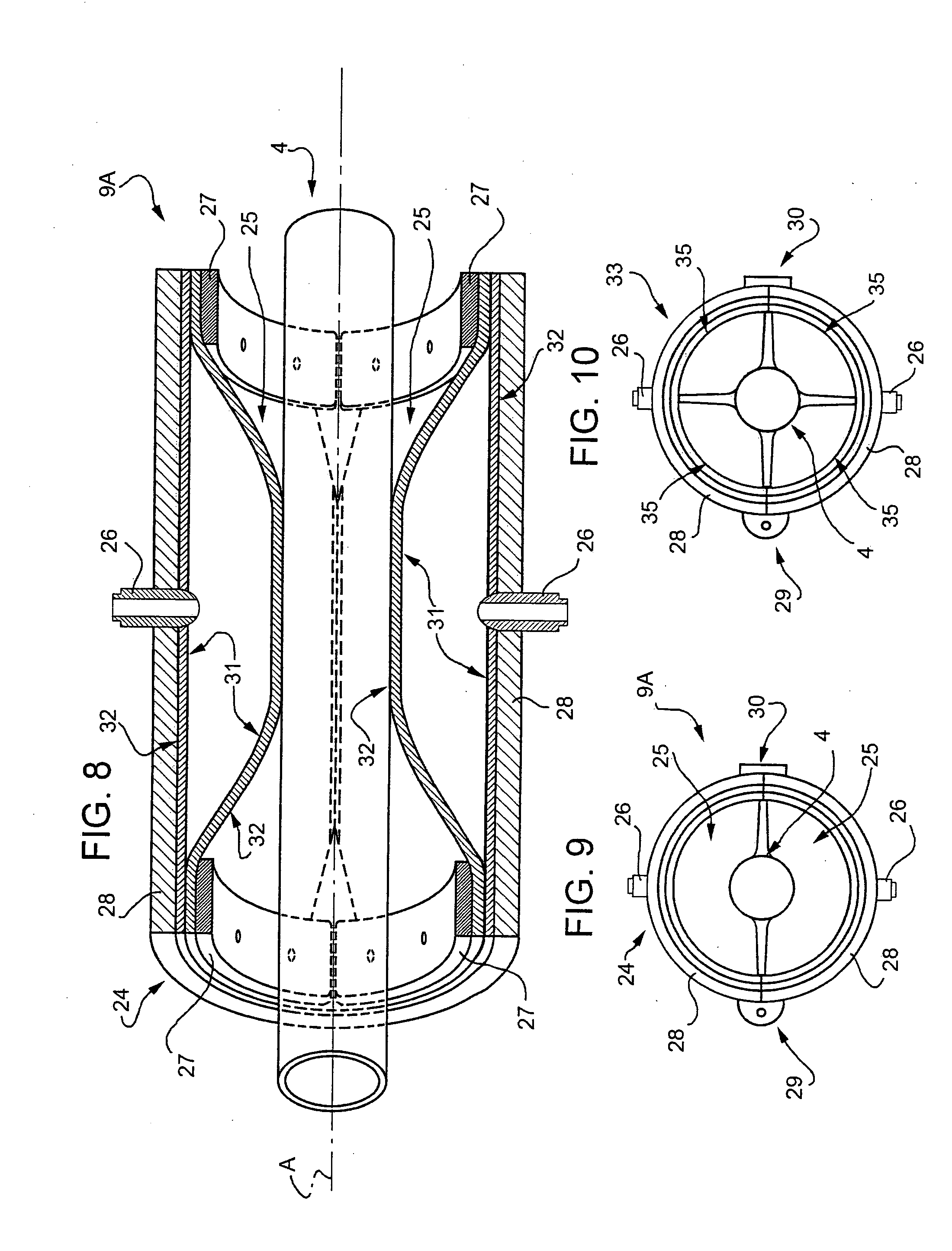
[0006]It is an object of the present invention to provide a gripper designed to eliminate the above drawbacks of the known art, and which, in particular, defines a sufficiently large grip surface area even along continuous elongated members with highly irregularly shaped cross sections.

Problems solved by technology

This type of gripper also fails to effectively grip continuous elongated members of widely differing diameters, on account of each ring being designed for a circular-section pipeline slightly smaller in diameter than the inside diameter of the tubular structure.
Moreover, the rings fail to define a sufficiently large grip surface area.
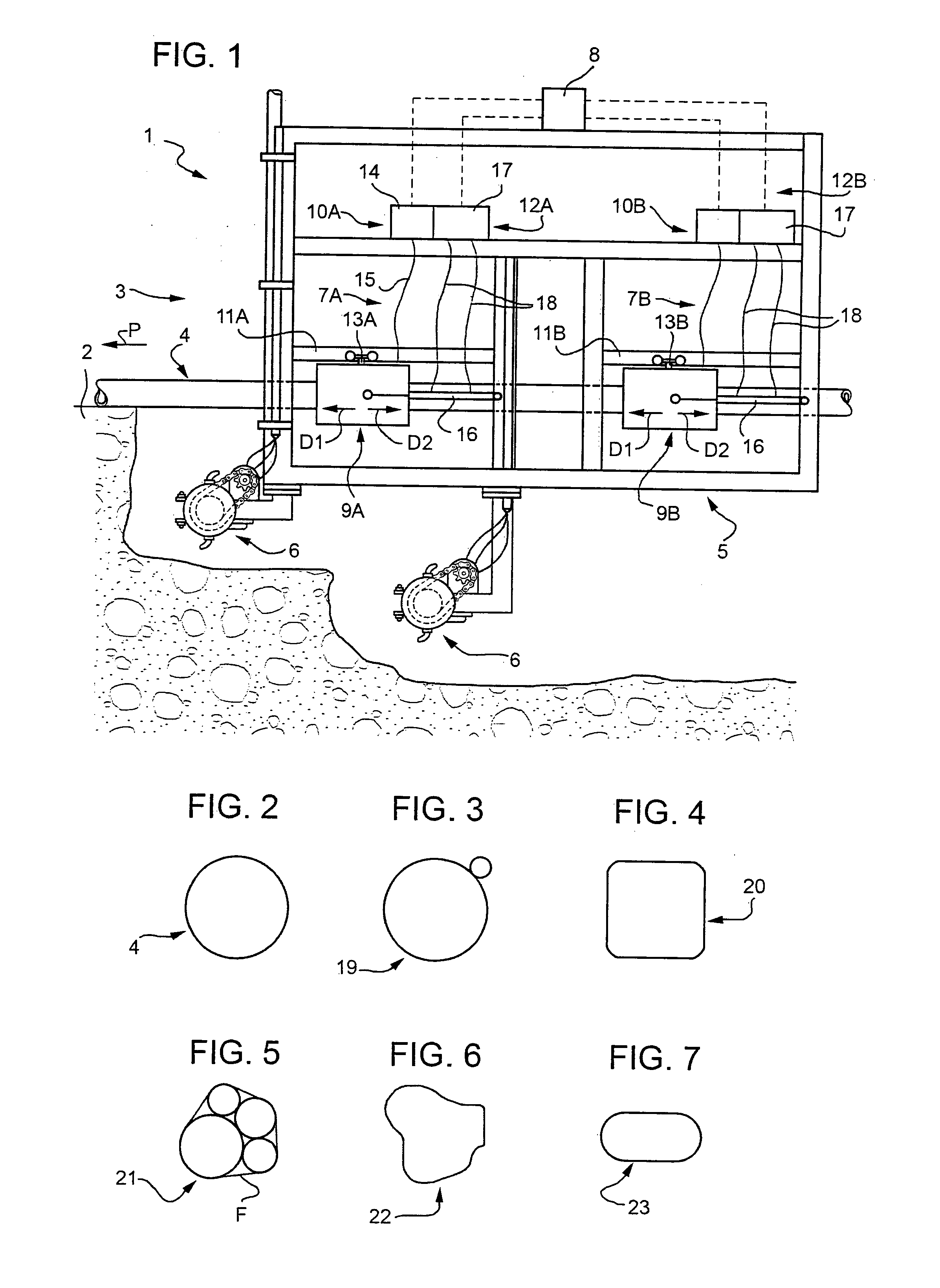
Which means the cross sections may assume any number of shapes, for which known grippers fail to provide a sufficiently large grip surface area.

Method used


Image

  • Gripper for continuous elongated members, vehicle movable along a continuous elongated member, and method of advancing the vehicle
  • Gripper for continuous elongated members, vehicle movable along a continuous elongated member, and method of advancing the vehicle
  • Gripper for continuous elongated members, vehicle movable along a continuous elongated member, and method of advancing the vehicle

Examples


Embodiment Construction

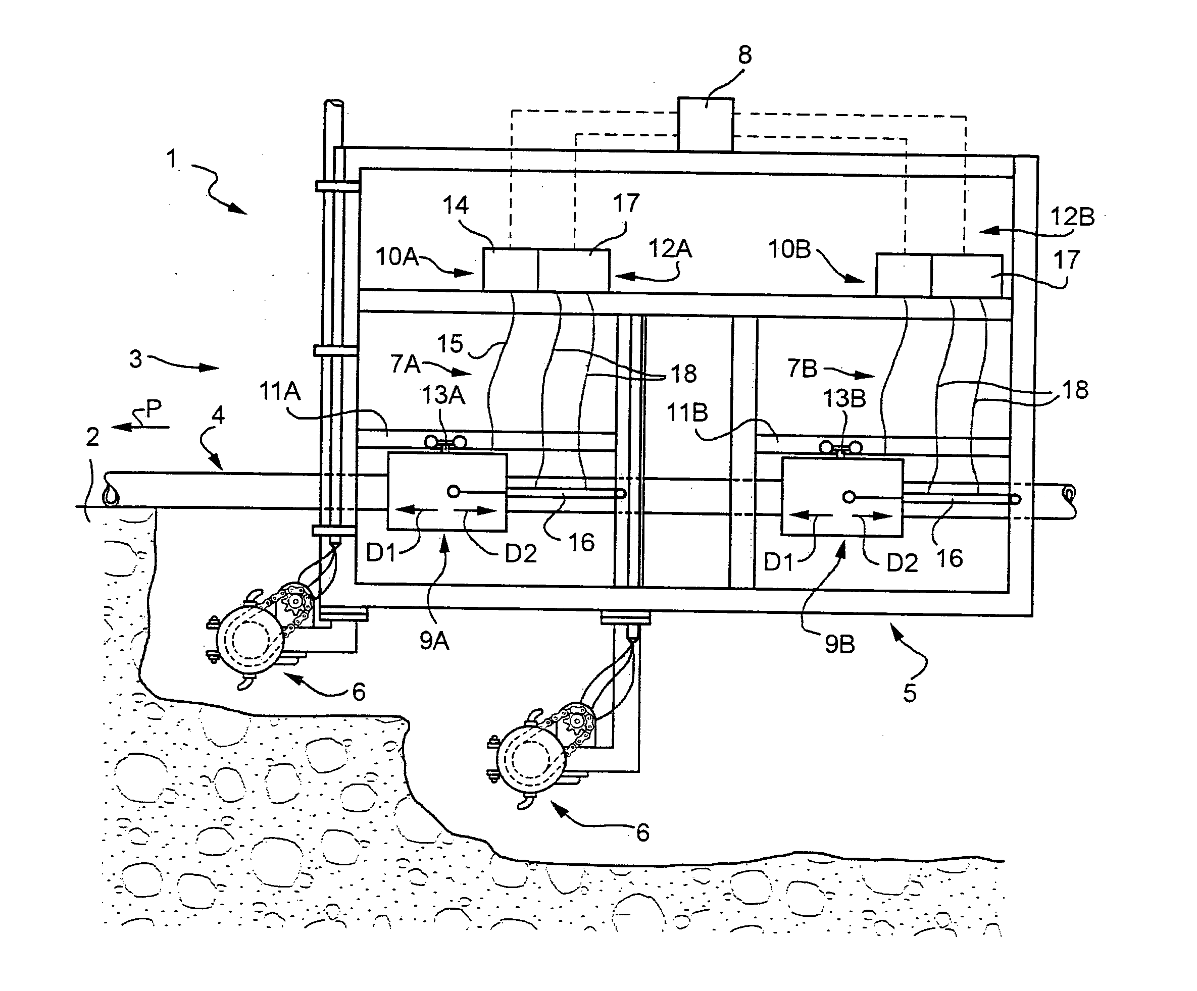
[0021]Number 1 in FIG. 1 indicates as a whole a vehicle for burying continuous elongated members in the bed 2 of a body of water 3.

[0022]For the purpose of the present description, the term “body of water” is intended to mean any stretch of water, such as sea, ocean, lake, etc., and the term “bed” is intended to mean the concave layer of the earth's crust containing the body of water.

[0023]Vehicle 1 is designed to bury a continuous elongated member 4—in the example shown, an underwater pipeline—extending along a given path P on bed 2, and laid beforehand on bed 2 by a known laying vessel (not shown). Vehicle 1 is controlled by a support vessel (not shown), and comprises a frame 5; two tools 6—in the example shown, cutters—fitted to frame 5; two gripping units 7A, 7B fitted to frame 5; and a control unit 8. Continuous elongated member 4 actually guides and anchors vehicle 1, which, as it advances, cuts into a layer of bed 2 directly beneath continuous elongated member 4, to sink cont...


PUM


Abstract

A gripper for selectively gripping continuous elongated members can include a tubular supporting structure extending along a given axis and designed to surround a continuous elongated member. The gripper can also include at least two inflatable bags within the tubular structure and in the shape of complementary cylindrical sectors.

Description

TECHNICAL FIELD [0001]The present invention relates to a gripper for selectively gripping continuous elongated members; a vehicle which employs such a gripper to move forward; and a method of advancing the vehicle.BACKGROUND ART [0002]The term “continuous elongated member” used in the present invention applies to pipelines and cables of finite length, but much longer than the gripper.[0003]Continuous elongated members are laid both on land and on underwater beds, normally to transport fossil fuel and electric power over distances of kilometers; are normally buried and circular in cross section; and are handled using grippers comprising jaws with grip surfaces complementary to the shape and size of the continuous elongated member, as shown, for example, in GB 2,364,758. Using this type of gripper, the jaws must be adapted to continuous elongated members of different diameters, to achieve a sufficient grip surface area along the jaws.[0004]Another type of gripper, described in GB 2,44...

Claims


Application Information

Patent Timeline
IPC IPC(8): B25J15/00F16L1/16B63G8/08B61B13/12
CPCE02F5/101F16L1/16E02F5/104
Inventor FASSETTA, ALBERTOVIELMO, PAOLO
Owner SAIPEM SPA
Learn More