Lid lock with magnetic Anti-tamper feature

a magnetic lock and anti-tamper technology, applied in the field of home appliances, can solve the problem of reducing the possibility of casual tampering

Active Publication Date: 2012-12-13
ILLINOIS TOOL WORKS INC
View PDF14 Cites 28 Cited by
  • Summary
  • Abstract
  • Description
  • Claims
  • Application Information

AI Technical Summary

Benefits of technology

[0023]It is thus a feature of at least one embodiment of the invention to eliminate the need for a separate lid switch operator.
[0024]Motion of the bolt to disengage from the latch when the blocking element is received by the trap may cause an abutting of the blocking element against a frangible portion of the trap which when broken prevents activation of the locking switch.
[0025]It is thus a feature of at least one embodiment of the invention to detect damage to the latch by forcible opening that might prevent future locking.
[0026]The frangible portion of the trap may support a spring element away from an opening into which the blocking element may be received such that removal of the frangible element causes the spring element to occlude the opening.
[0027]It is thus a feature of at least one embodiment of the invention to provide a simple method of signaling damaged by defeating the blocking element and thus deactivating the lock signal.

Problems solved by technology

The use of a magnetic actuator reduces the possibility of casual tampering.

Method used


Image

  • Lid lock with magnetic Anti-tamper feature
  • Lid lock with magnetic Anti-tamper feature
  • Lid lock with magnetic Anti-tamper feature

Examples


Embodiment Construction

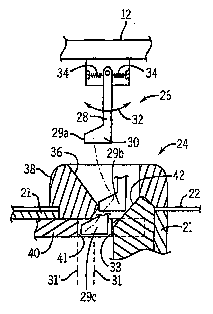
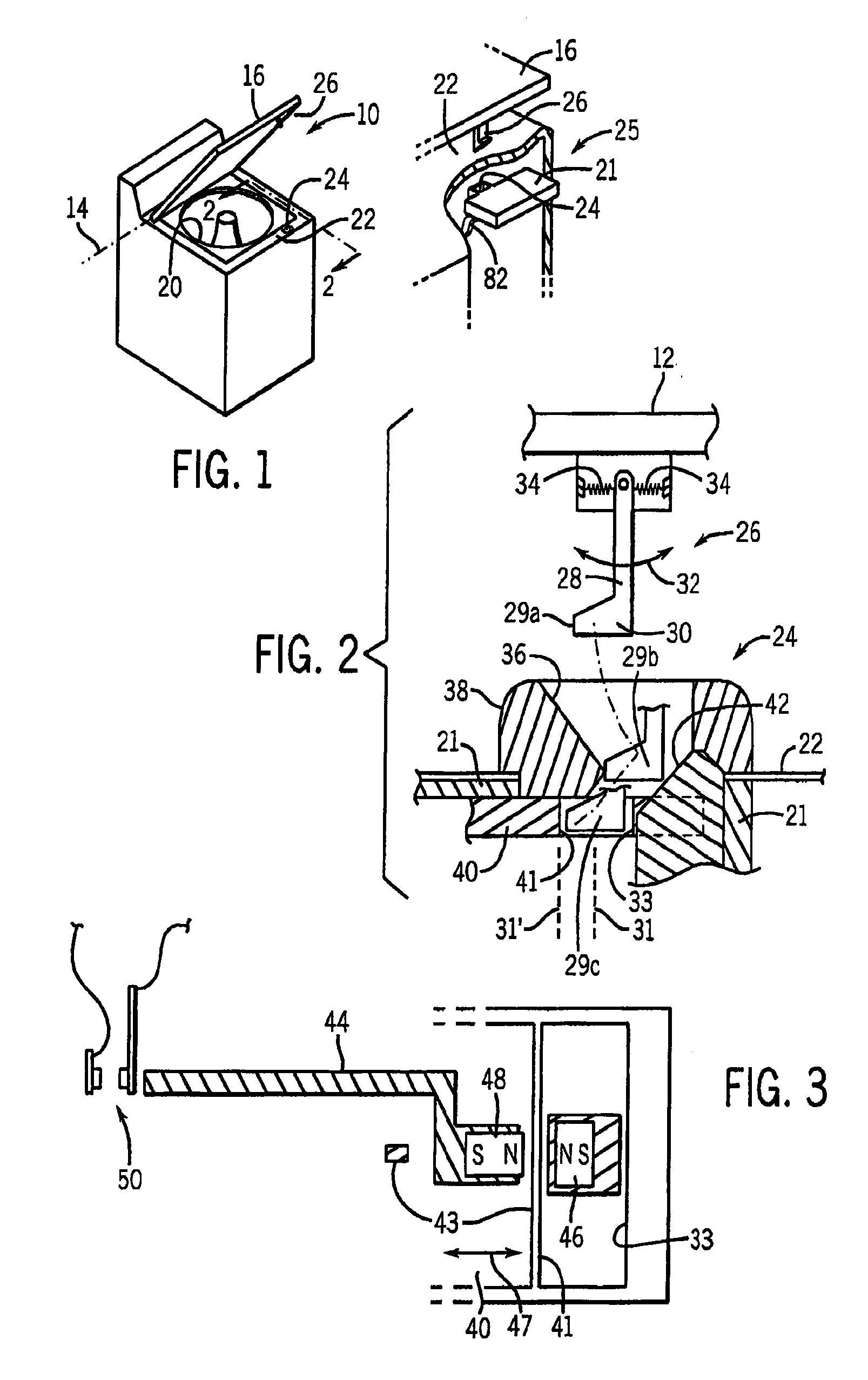
[0045]Referring now to FIG. 1, a top loading washing machine 10 suitable for use with the present invention includes a lid 12 opening upward about a horizontal lid hinge axis 14. The lid hinge axis 14 is positioned near the top rear edge of the washing machine 10 so that a rear edge 16 of the lid 12 may raise and lower to expose and cover an opening 20 through which clothing may be inserted into the spin basket. A front-loading washing machine (not shown) is also suitable for use with the present invention as will be apparent to those of ordinary skill in the art from the following description with an appropriate adjustment of the orientation.

[0046]A horizontal surface of the top 22 of the washing machine 10, at the periphery of the opening 20, may support a strike aperture 24 form in a housing 21 of a latch 25 fastened to the underside of the top 22. The strike aperture 24 opens upward to receive a downwardly extending bolt 26 attached to an underside of the lid 12. Both the strike...


PUM


Abstract

A latch for a washing machine or other appliance provides two interengaging elements on a lid and housing each having a magnet oriented for mutual repulsion. Proper repulsion of the magnets is necessary to signal that the lid is properly closed such as may be used to determine if the appliance may be locked and safely operated, for example, in a clothes spinning mode.

Description

CROSS-REFERENCE TO RELATED APPLICATION[0001]This application claims the benefit of U.S. provisional application 61 / 309,208 filed Mar. 1, 2010 and hereby incorporated by reference.FIELD OF THE INVENTION[0002]The present invention relates to home appliances such as clothes washing machines and the like and in particular, to a lid locking mechanism that is highly resistant to tampering.BACKGROUND OF THE INVENTION[0003]The spin cycle of a washing machine removes water centrifugally from wet clothes by spinning the clothes at high speed in a spin basket. In order to reduce the possibility of injury to the user during the spin cycle, it is known to use an electronically actuated lock for holding the washing machine lid in the closed position. U.S. Pat. Nos. 6,363,755; 5,823,017; and 5,520,424, assigned to the present assignee and hereby incorporated by reference, describe several locking mechanisms.[0004]In order to prevent tampering with the lock mechanism, for example, by holding the li...

Claims


Application Information

Patent Timeline
Patent Type & Authority Applications(United States)
IPC IPC(8): E05C19/12H02G3/18E05C19/06
CPCD06F37/42D06F39/14H01H36/0073H01H36/00E05C19/026H02G3/04Y10T292/0911Y10T292/11D06F37/28
Inventor HAPKE, KENYON A.BRAGG, JOEL C.HINTZ, MICHAEL K.MCDONALD, RANDY S.HECKENKAMP, MARK R.OLSON, JONATHAN H.TENGLER, ADRIAN J.SULIK, JAROD M.
Owner ILLINOIS TOOL WORKS INC
Why Eureka
Try Eureka