Method of modifying the surface shape of a wind turbine rotor blade and tool for use in this method

Inactive Publication Date: 2012-12-13
SIEMENS AG
View PDF8 Cites 9 Cited by
  • Summary
  • Abstract
  • Description
  • Claims
  • Application Information

AI Technical Summary

Benefits of technology

[0012]Although a one piece mould works fine in many cases it might be useful if the mould comprises at least two halves. This development allows the mould to enclose as space that fully extends around the wind turbine rotor blade

Problems solved by technology

In particular, a seamless or almost seamless connection of a shape modifying element to the surface of the wind turbine rotor blade is difficult to a

Method used


Image

  • Method of modifying the surface shape of a wind turbine rotor blade and tool for use in this method
  • Method of modifying the surface shape of a wind turbine rotor blade and tool for use in this method
  • Method of modifying the surface shape of a wind turbine rotor blade and tool for use in this method

Examples


Embodiment Construction

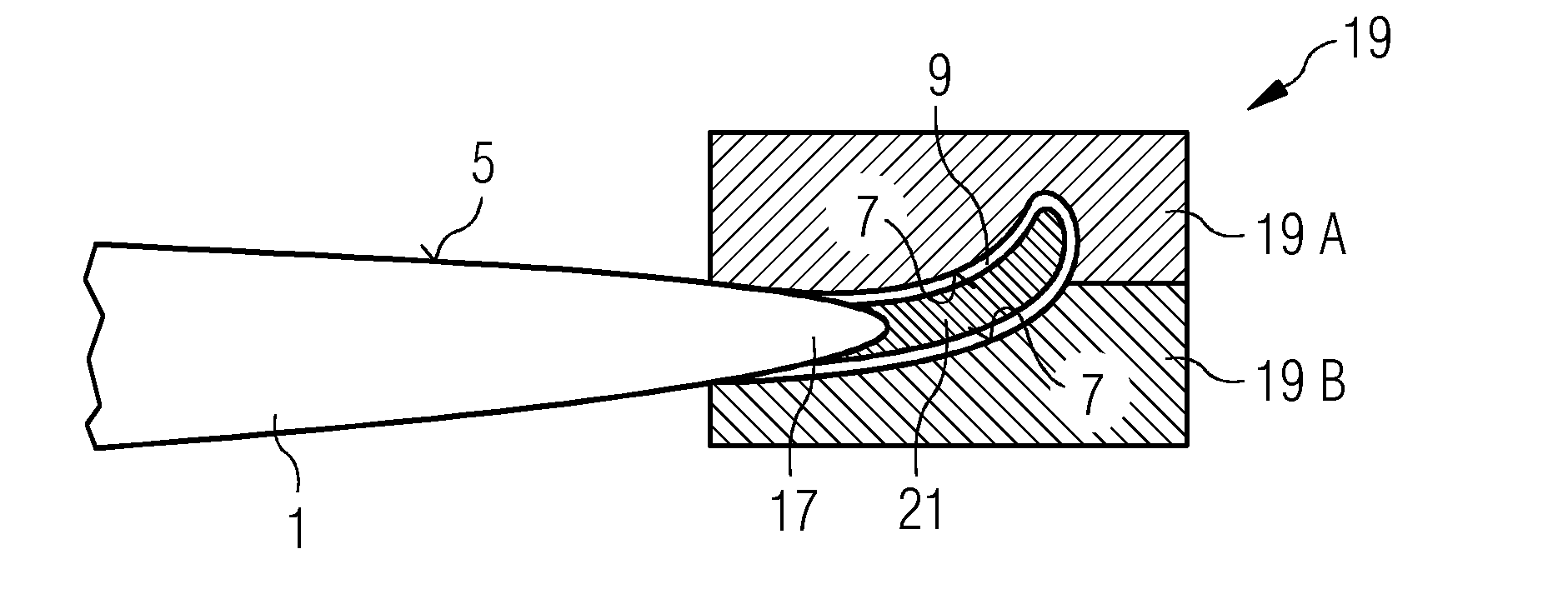
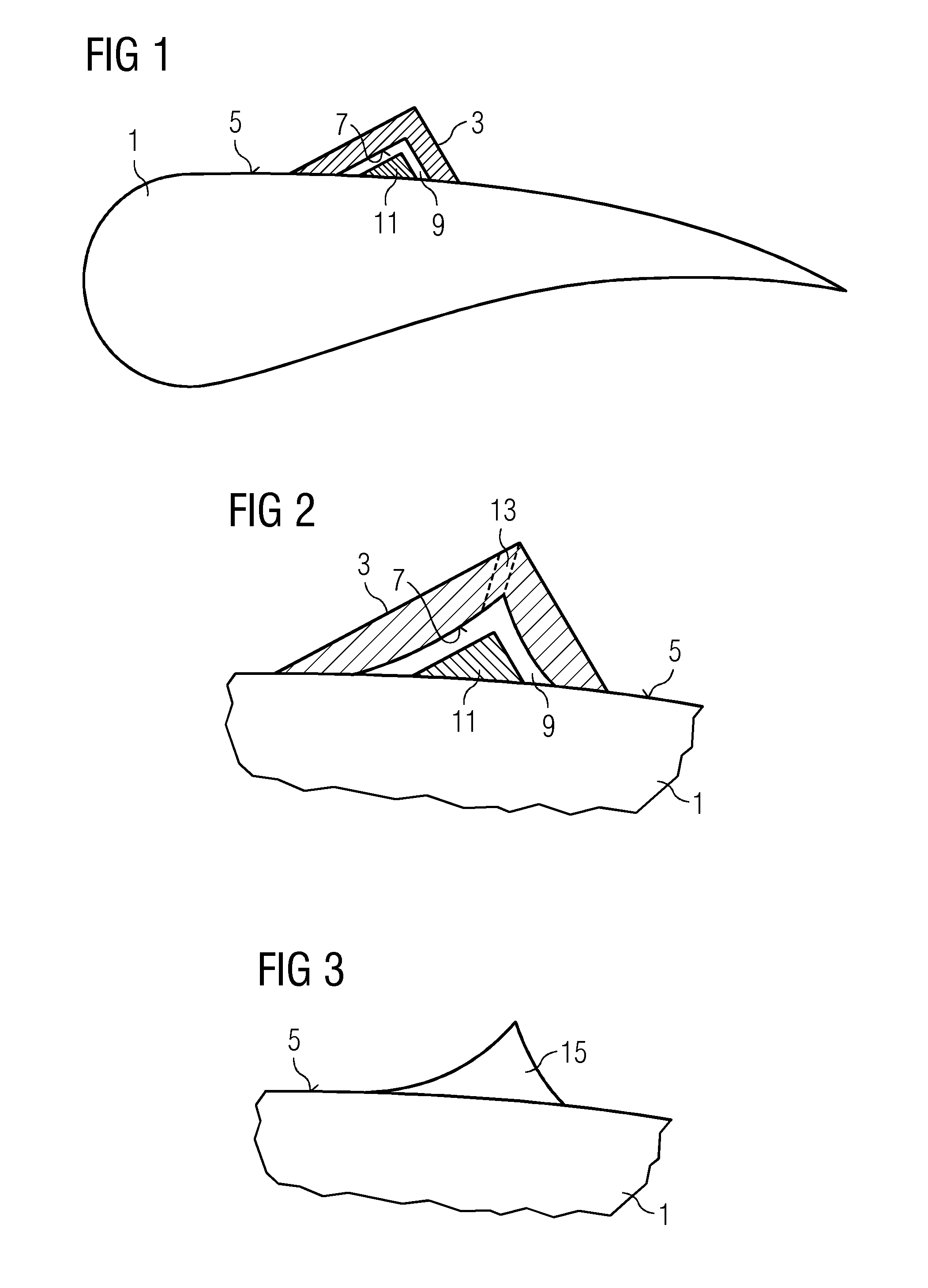
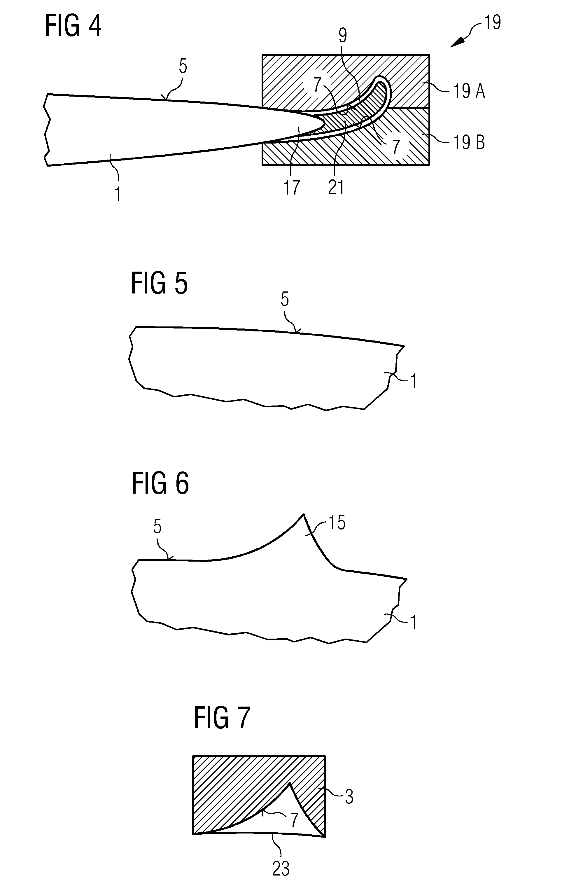
[0021]The inventive method will now be described with respect to FIGS. 1 to 4, where FIGS. 1 to 3 schematically show casting of a turbulator while FIG. 4 schematically shows casting of a winglet.

[0022]According to the inventive method, shape modifying elements like turbulators, flaps, spoilers, winglets, etc. are directly cast on the surface of a wind turbine rotor blade. FIG. 1 schematically shows a wind turbine rotor blade 1 the surface of which is to be modified in a sectional view together with a mould 3 set on the unmodified surface 5 of the wind turbine rotor blade. In the present embodiment, the mould 3 is made of a single piece although a mould made of two or more pieces may also be used. An inner surface 7 of the mould 3 and the unmodified surface 5 of the blade 1 covered by the mould 3 together form an enclosed space 9 that defines the shape of a turbulator that is cast on the blade surface 5 as shape modifying element in the present embodiment.

[0023]Inside the enclosed sp...


PUM

PropertyMeasurementUnit
Flow rateaaaaaaaaaa
Shapeaaaaaaaaaa
Adhesivityaaaaaaaaaa

Abstract

A method of modifying the surface shape of a wind turbine rotor blade is provided in which a shape modifying element is cast on a surface of the wind turbine rotor blade. A mould includes an inner mould surface, the shape of which is defined according to a result of subtracting an unmodified surface shape of the wind turbine rotor blade from a desired modified surface shape.

Description

CROSS REFERENCE TO RELATED APPLICATIONS[0001]This application claims priority of European Patent Office Application No. 11168880.0 EP filed Jun. 07, 2011. All of the applications are incorporated by reference herein in their entirety.FIELD OF INVENTION[0002]The present invention relates to a method of modifying the surface shape of a wind turbine rotor blade as well as to a tool used in modifying the surface shape of a wind turbine rotor blade.BACKGROUND OF INVENTION[0003]Modifications to surface shapes of wind turbine rotor blades are usually done to alter the aerodynamic properties of the blades. For example, U.S. Pat. No. 7,914,259 B2 describes the use of vortex generators on wind turbine rotor blades. Such vortex generators can be used for counteracting flow separation and stall, and for noise reduction. The vortex generators described in U.S. Pat. No. 7,914,259 B2 are attached to the wind turbine rotor blades by attachment means like screws, bolts, rivets, or by welding or glui...

Claims


Application Information

Patent Timeline
IPC IPC(8): B29C39/10
CPCB29C70/74F05B2230/30F05B2240/122F03D1/0641F05B2230/80Y02E10/721F05B2240/3062Y02E10/72Y02P70/50
Inventor STEGE, JASON
Owner SIEMENS AG
Why Eureka
Try Eureka