Device for enhanced mechanical stabilization

Inactive Publication Date: 2012-12-13
FARIN AZADEH
View PDF1 Cites 8 Cited by
  • Summary
  • Abstract
  • Description
  • Claims
  • Application Information

AI Technical Summary

Benefits of technology

[0008]In an embodiment, the invention includes an apparatus, comprising a shaft with exterior threading; a head affixed to the shaft; at least one stabilization apparatus configured in the shaft; and an actuator movably positioned at least partially within the shaft and having an end positioned in the head, the actuator to actuate the at least one stabilization apparatus. The head may further comprise a receiving portion to receive a tool. The head may further comprise a receiving portion adapted to interact with additional apparatuses, rods or other mechanical components. The apparatus may comprise two, three, four or five stabilization apparatuses. The apparatus may comprise at least two stabilization apparatuses that are the same as one another or are each different from one another. Each of the at least one stabilization apparatus may comprise one or more stabilizing elements, wherein upon actuation of each of the at least one stabilization apparatuses, the one or more stabilizing elements each deploy in a generally outward direction from a central axis of the shaft. Each of the at least one stabilization apparatus may comprise at least two stabilizing elements. Each of the at least one stabilization apparatus may comprise three, four or five stabilizing elements. Upon reverse actuation of each of the at least one stabilization apparatuses, the one or more stabilizing elements may each retract into the shaft. The actuator may further comprise a receiving mechanism to receive a tool. The actuator may be adapted to be actuated by rotation relative to the head and the shaft. The actuator may be adapted to be actuated by depression into the head and the shaft. The actuator may comprise a series of ridges parallel to the central axis of the shaft; the stabilization apparatus may comprise at le

Problems solved by technology

This enhanced fixation mechanism would reduce the likelihood that the devices loosen after insertion into bone or fall out of bone entirely, resulting in a failed construct.
A failed device that is poorly attached to bone co

Method used


Image

  • Device for enhanced mechanical stabilization
  • Device for enhanced mechanical stabilization
  • Device for enhanced mechanical stabilization

Examples


Embodiment Construction

[0031]All references cited herein are incorporated by reference in their entirety as though fully set forth. Unless defined otherwise, technical and scientific terms used herein have the same meaning as commonly understood by one of ordinary skill in the art to which this invention belongs. One skilled in the art will recognize many methods and materials similar or equivalent to those described herein, which could be used in the practice of the present invention. Indeed, the present invention is in no way limited to the methods and materials described.

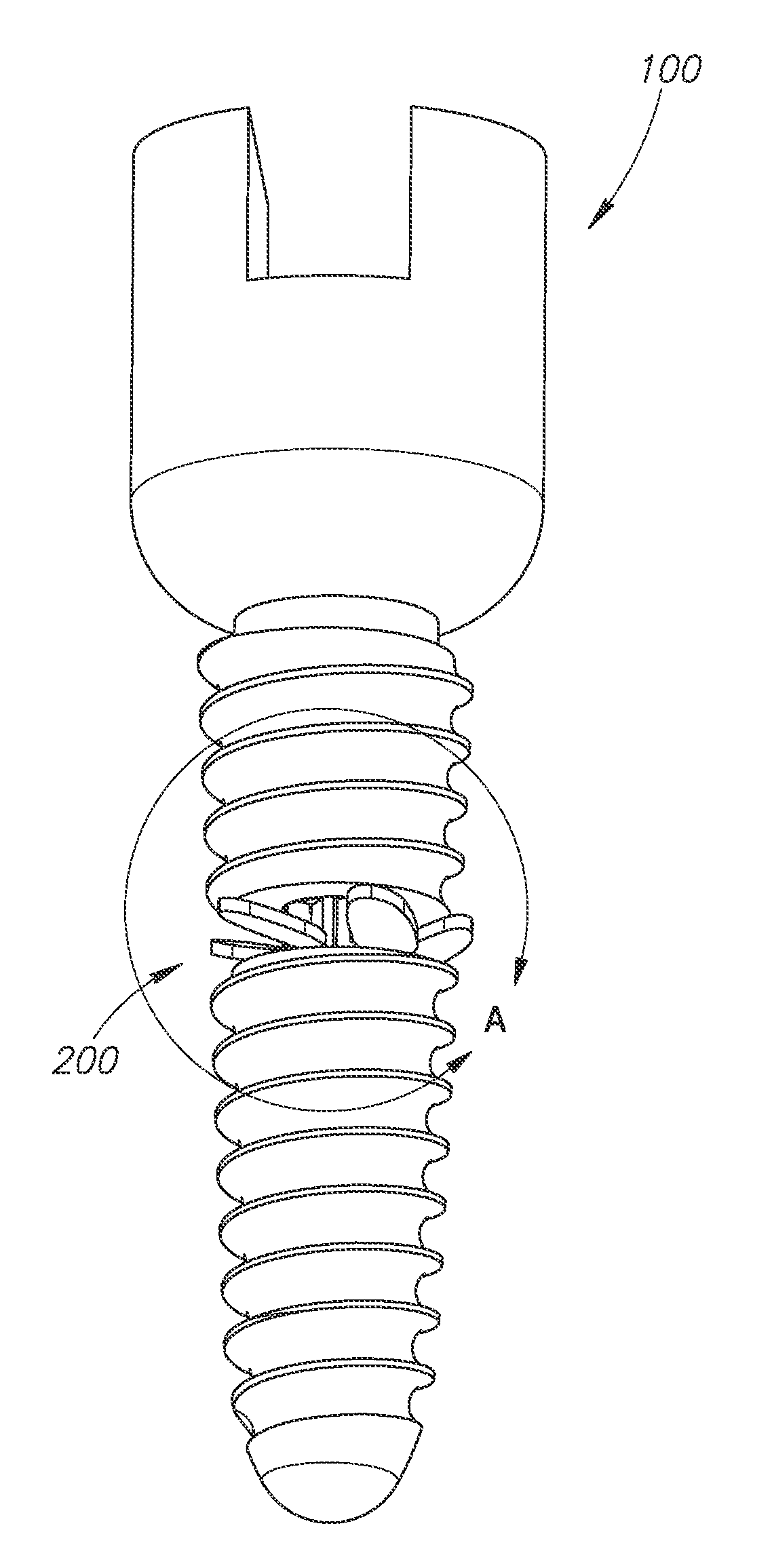
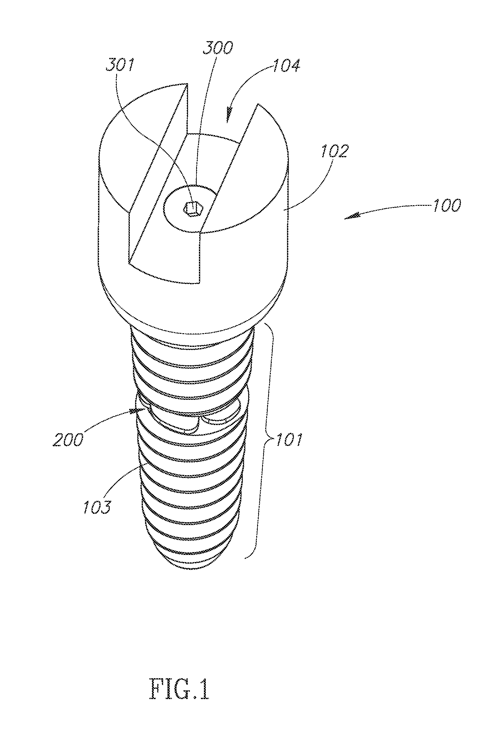
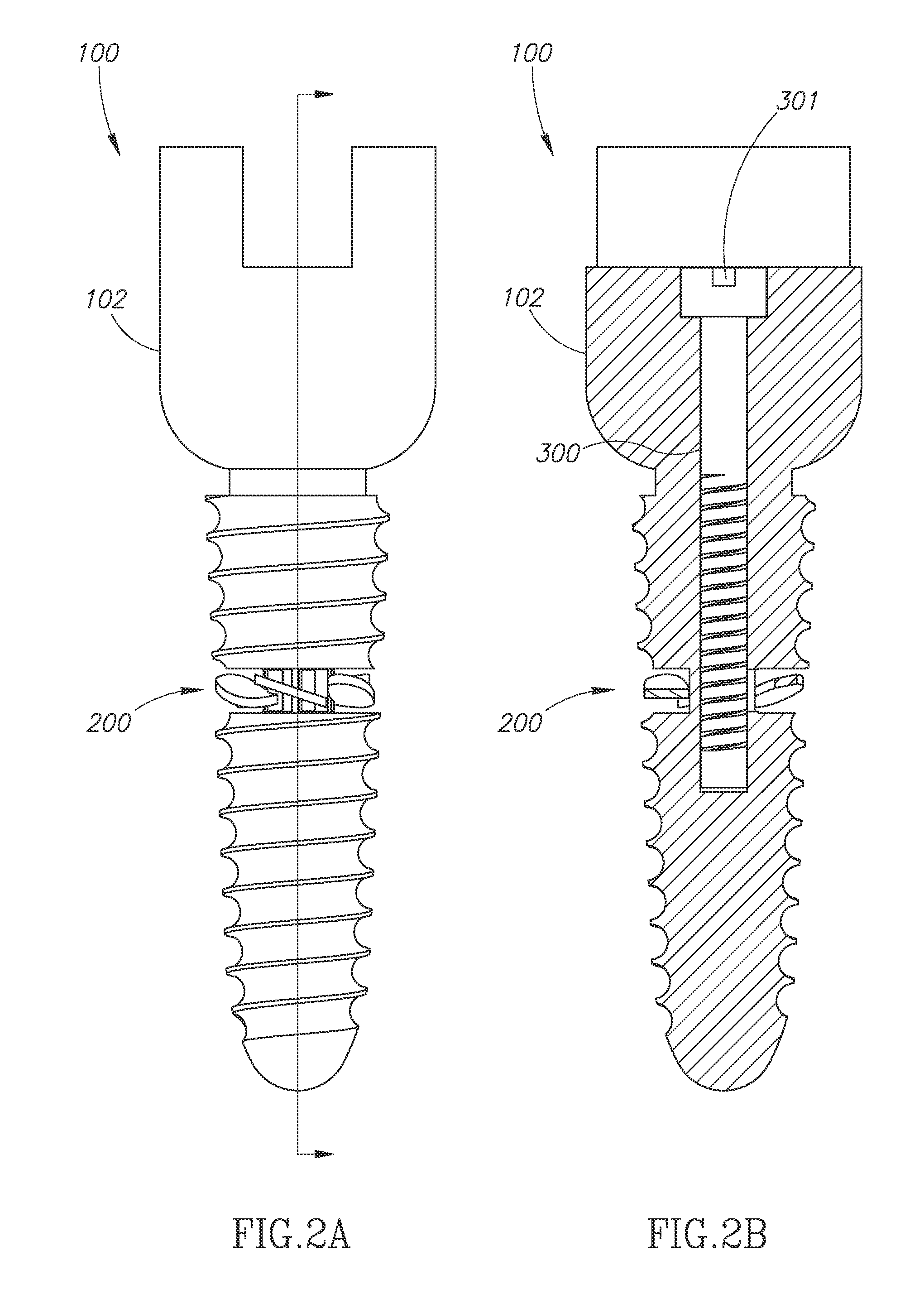
[0032]The invention relates to a device that provides enhanced mechanical fixation and / or stabilization, as well as methods for its use. The terms “stabilization” and “stabilizing” are used herein with reference to both the end result achieved through use of the inventive devices and methods, as well as in the naming of certain elements included within the inventive device (e.g., the “stabilization apparatus” or the “stabilizing elemen...


PUM


Abstract

The invention relates to a device that provides enhanced mechanical stabilization, as well as methods for its use. In various embodiments, the device is configured in a manner similar to a conventional screw, but with mechanical elements that afford greater fixation and stability and that lessen the likelihood that the device loosens after insertion into a substrate and/or falls out of the substrate entirely or releases its interaction with the substrate. Moreover, the device may have better pullout strength as compared with conventional screws and screw-type devices used in a range of applications.

Description

BACKGROUND OF THE INVENTION[0001]1. Field of the Invention[0002]The present invention is directed generally to a device that provides enhanced mechanical fixation and stabilization, as well as methods for its use.[0003]2. Description of the Related Art[0004]All publications cited herein are incorporated by reference in their entirety to the same extent as if each individual publication or patent application was specifically and individually indicated to be incorporated by reference. The following description includes information that may be useful in understanding the present invention. It is not an admission that any of the information provided herein is prior art or relevant to the presently claimed invention, or that any publication specifically or implicitly referenced is prior art.[0005]Common screws are used for a variety of purposes and in a variety of settings. They range widely in size, in the materials used in their construction, in the configuration of their heads (i.e., ...

Claims


Application Information

Patent Timeline
IPC IPC(8): A61B17/86F16B35/00
CPCA61B17/8625A61B17/8685A61B17/864
Inventor FARIN, AZADEH
Owner FARIN AZADEH
Why Eureka
Try Eureka