Strain relieved lead routing in burr hole plug for deep brain stimulation

a burr hole plug and lead routing technology, applied in the field of attachment devices for elongated medical devices, can solve problems such as the effect of reducing the therapy effect of patients

Active Publication Date: 2012-12-13
BOSTON SCI NEUROMODULATION CORP
View PDF2 Cites 22 Cited by
  • Summary
  • Abstract
  • Description
  • Claims
  • Application Information

AI Technical Summary

Benefits of technology

[0012]In one method the second groove and the third groove are circumferentially spaced from each other by ninety degrees. The proximal end of the medical device may be looped within the aperture of the plug base between

Problems solved by technology

Thus, lead displacements of less than a millimeter ma

Method used


Image

  • Strain relieved lead routing in burr hole plug for deep brain stimulation
  • Strain relieved lead routing in burr hole plug for deep brain stimulation
  • Strain relieved lead routing in burr hole plug for deep brain stimulation

Examples


Embodiment Construction

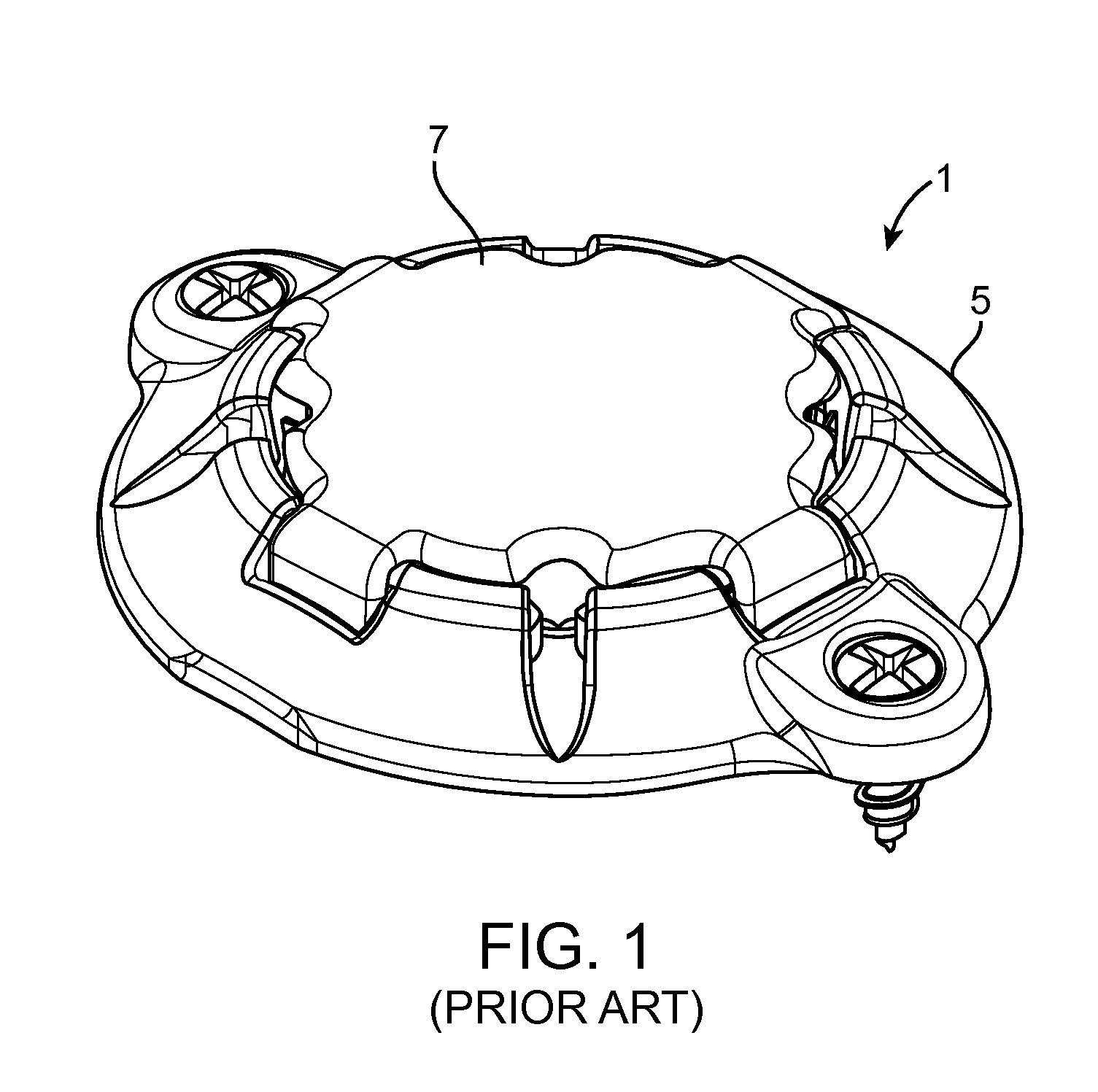
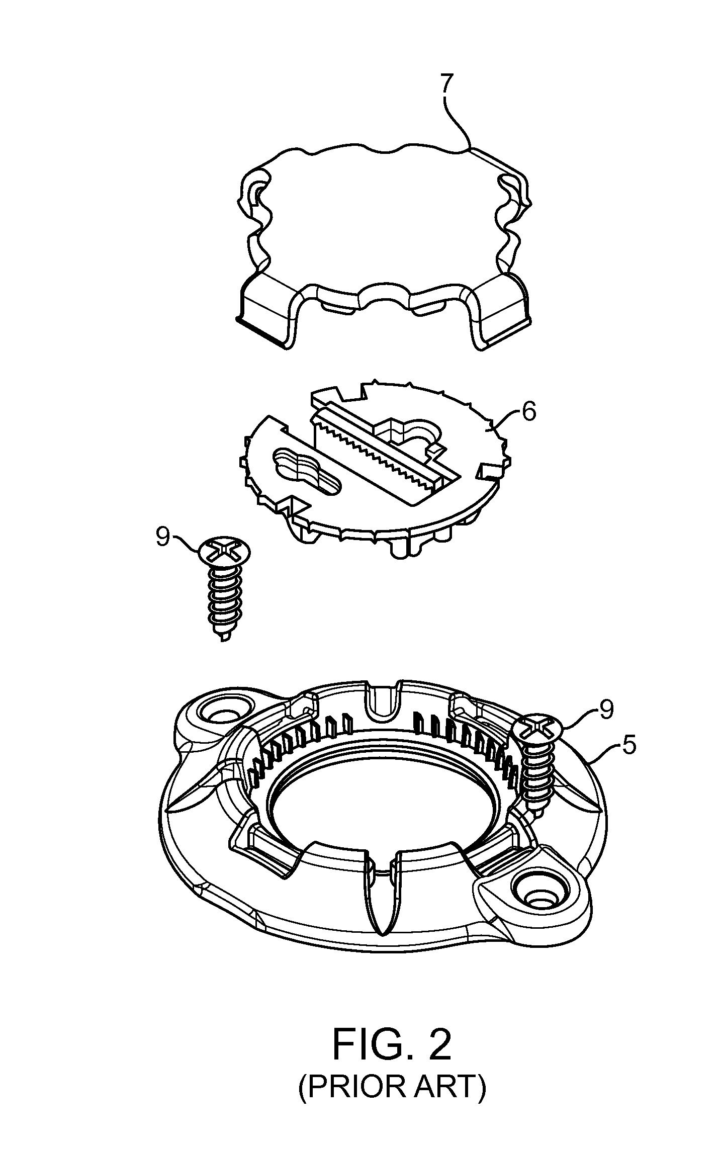
[0026]Referring to FIGS. 4-8, one method of implanting a stimulation lead within a brain of a patient using a burr hole plug will now be described. Although the exemplary method is described in the context of the burr hole plug 1 and stimulation lead 3 previously described with respect to FIGS. 1-3, the method described herein can be used with other types of burr hole plugs and stimulation leads.

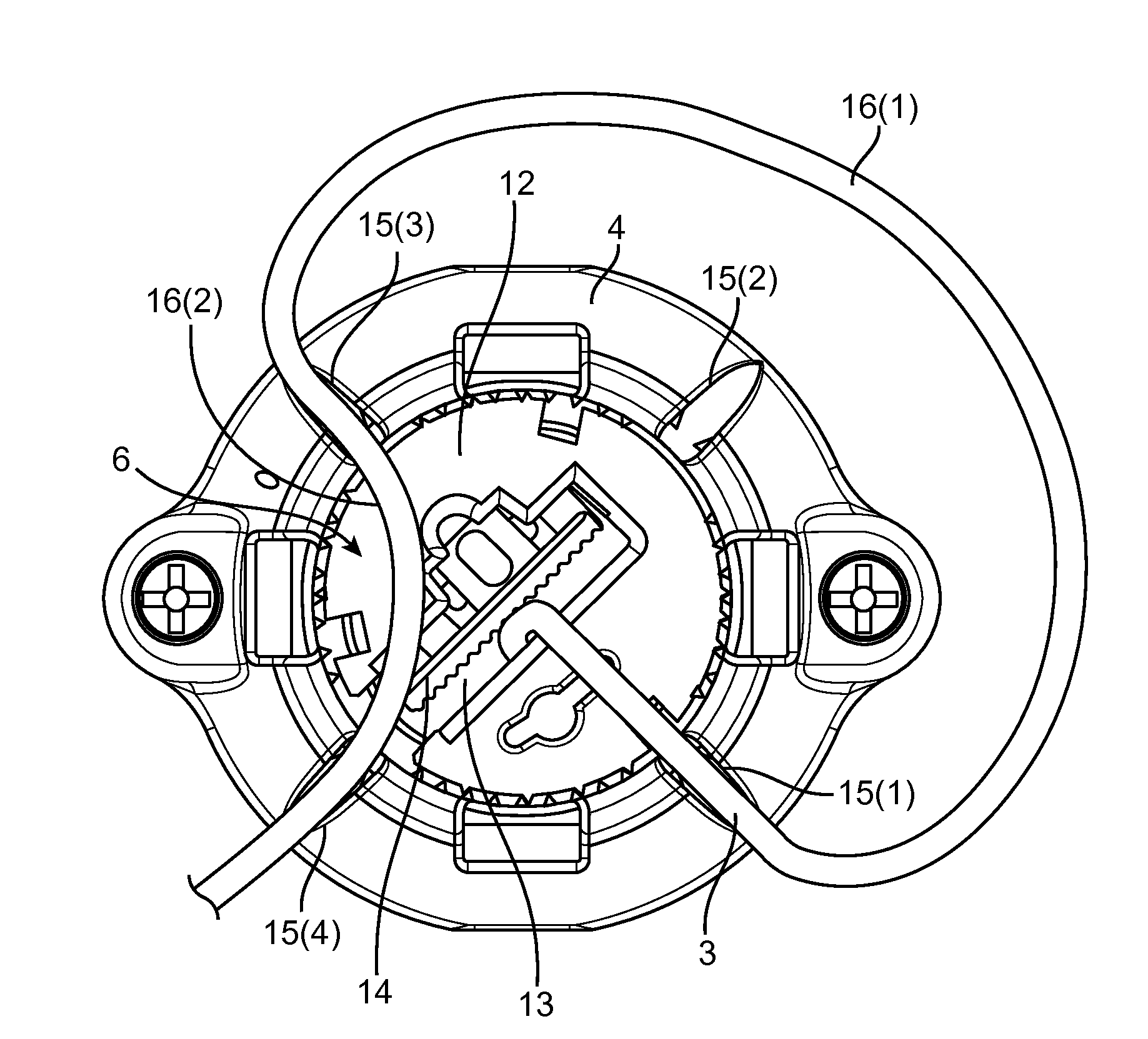
[0027]Referring first to FIG. 4, the plug base 4 is placed on top of the cranium 8 of the patient, such that plug base 4 is disposed around the burr hole 2 formed in the cranium 8, effectively aligning an aperture 10 of the plug base 4 with the burr hole 2. The plug base 4 may have centering tabs or an annular flange (not shown) that can be disposed within the burr hole 2 to facilitate centering of the plug base 4 relative to the burr hole 2. The plug base 4 is then anchored to the cranium 8 using suitable fasteners, such as screws 9 introduced through screw holes 11 formed in the plug base ...


PUM


Abstract

A method of performing a medical procedure comprises introducing a medical device through a cranial burr hole into the brain tissue, mounting a plug base around a cranial burr hole, securing the medical device within the aperture of the plug base, seating a proximal end of the medical device within a first groove of the plug base, such that the proximal end exits the aperture of the plug base through the first groove, looping the proximal end from the first groove to a second groove in the plug base, seating the proximal end within the second groove, such that the proximal end extends across the aperture of the plug base from the second groove, and seating the proximal end within a third groove of the plug base, such that the proximal end exits the plug base aperture through the third groove.

Description

RELATED APPLICATION DATA[0001]The present application claims the benefit under 35 U.S.C. §119 to U.S. provisional patent application Ser. No. 61 / 494,820, filed Jun. 8, 2011. The foregoing application is hereby incorporated by reference into the present application in its entirety.FIELD OF THE INVENTION[0002]The present inventions relate to apparatus for securing elongated medical devices, such as catheters or leads, within a cranial burr hole.BACKGROUND OF THE INVENTION[0003]Deep brain stimulation (DBS) and other related procedures involving implantation of electrical stimulation leads within the brain of a patient are increasingly used to treat disorders, such as Parkinson's disease, dystonia, essential tremor, seizure disorders, obesity, depression, restoration of motor control, and other debilitating diseases via electrical stimulation via stimulation of one or more target sites, including the ventrolateral thalamus, internal segment of globus pallidus, substantia nigra pars reti...

Claims


Application Information

Patent Timeline
IPC IPC(8): A61N1/05
CPCA61B19/20A61N1/0534A61B2562/187A61B2019/208A61N1/0539A61B90/10A61B2090/103
Inventor LOPEZ, THOMAS P.
Owner BOSTON SCI NEUROMODULATION CORP
Why Eureka
Try Eureka