Accessory for weapon muzzle

a technology for accessory and muzzle, which is applied in the field of accessory for weapon muzzle, can solve the problems of counteracting the desired anti-muzzle-climbing force, and achieve the effect of enhancing the natural appearance of the aperture, conducing to the desired functionality of the preferred muzzle brak

Inactive Publication Date: 2012-12-20
FORTUNE FORGE
View PDF3 Cites 1 Cited by
  • Summary
  • Abstract
  • Description
  • Claims
  • Application Information

AI Technical Summary

Benefits of technology

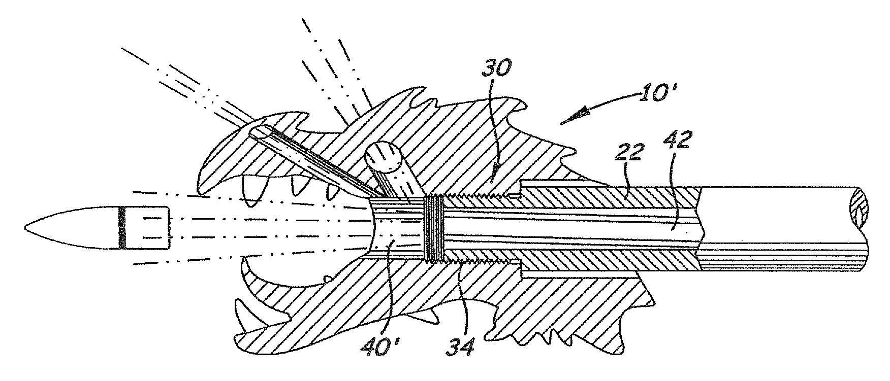
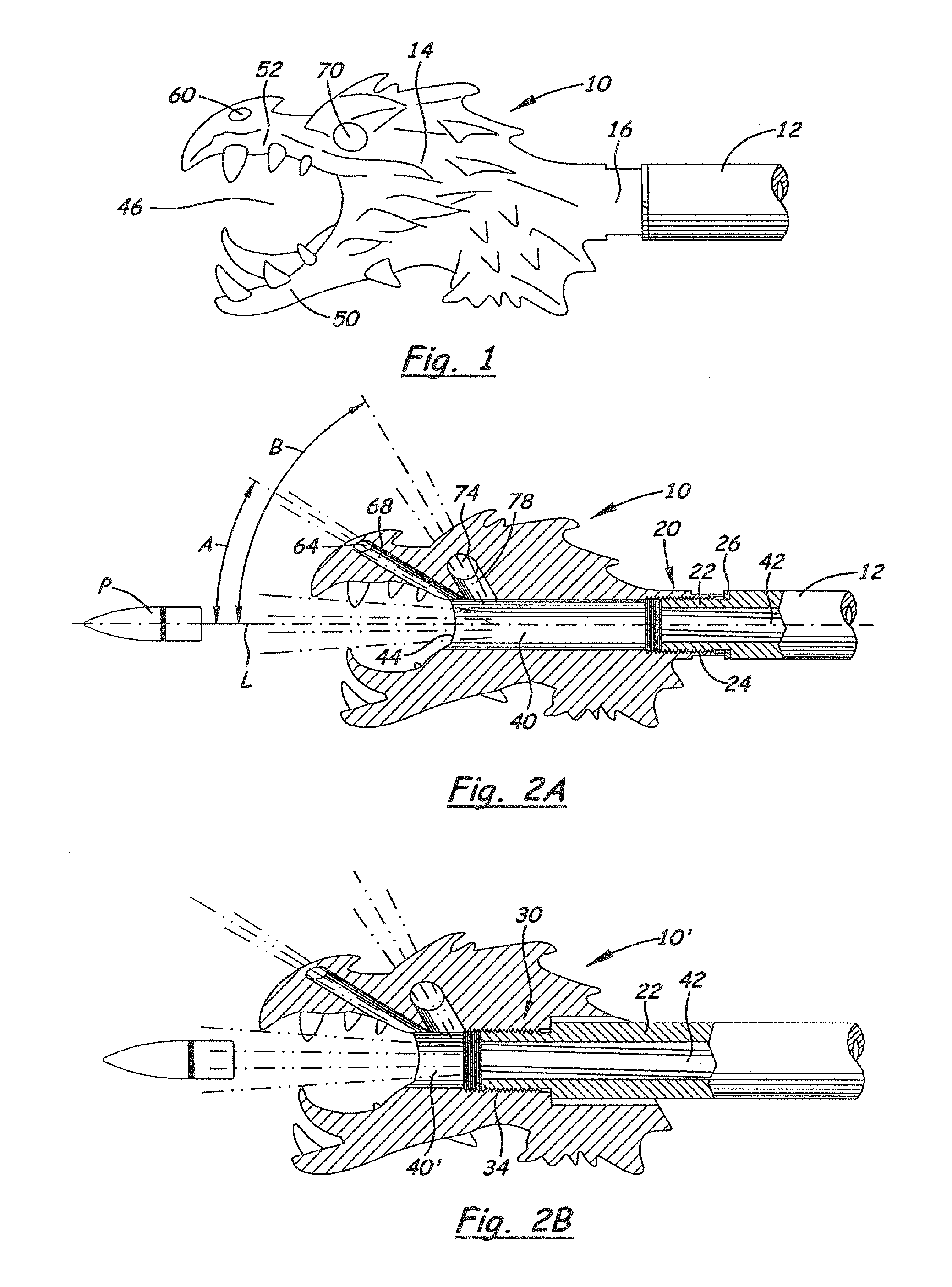
[0009]The mouth, eyes, nostril(s)/nose, and ear(s) of a face/head are naturally in an arrangement that is conducive to the desired functionality of the preferred muzzle brake. For example, a mouth-throat passageway may be used as the projectile path and exit, with the eyes, nose, and/or ears being above the mouth-throat. Therefore, the eyes, nose, and ears are above the projectile passageway and, when opened to the projectile passageway on an inner (lower) end and open to the air above the muzzle brake at an outer (upward) end, they provide the desired muzzle-brake functionality, that is, providing a downward force on the muzzle end. For example, opening up both eyes, both nostrils, and/or both ears directs gasses upward. Also, depending on the chosen shape and radial orientation (perpendicular, or forward, or rearward slanting) of the surfaces/conduits of the mouth, eyes, nostril(s)/nose and ear(s), additional forces on the muzzle (in addition to a downward force) may be created. For example, if said surfaces/conduits are perpendicular to the longitudinal axis, forces from impingement of gases on the perpendicular surfaces are expected to serve as anti-recoil forces, by forcing the muzzle forward (in addition to the...

Problems solved by technology

Downwardly-directed apertures are generally less-preferred as they may tend to counteract ...

Method used


Image

  • Accessory for weapon muzzle
  • Accessory for weapon muzzle
  • Accessory for weapon muzzle

Examples


Embodiment Construction

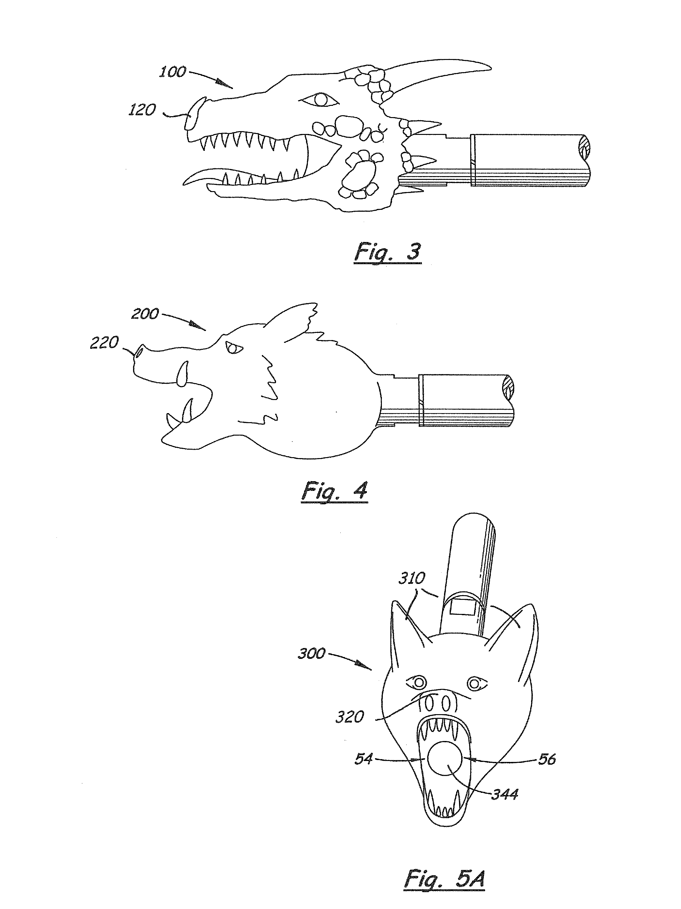
[0035]Referring to the Figures, there are shown several, but not the only, embodiments of the invented weapon muzzle accessory. FIGS. 1-16 portray some but not the only embodiments of the accessory intended for use as muzzle brakes. FIGS. 17-21 portray some but not the only embodiments of the accessory intended for use as flash suppressors.

[0036]The accessory is connected to the distal end of the muzzle, by various mean, for example, a threaded connection (FIGS. 1-10, 12-21 or a pinned connection (FIG. 11) or other means, including conventional connections for muzzle brakes or flash suppressors or silencers. The main functions of certain embodiments comprise exiting of the projectile via a passageway through the device, and exiting and directing of gasses through the projectile passageway and additional apertures. In addition, the outer form of the device, and the passageway and additional apertures if present, form the likeness of a creature, such as a human or human head, an anima...


PUM


Abstract

A weapon accessory in the likeness of a human, animal, mythical, or other creature, or a part of the creature, has a longitudinal passageway adapted to allow a projectile to exit the muzzle through the accessory. The projectile passageway opens through a mouth, eye, nose/nostril, or ear structure. Additional apertures selected from these structures, other than the one selected for the projectile exit, may be in fluid communication with the projectile passageway for directing exiting gasses in desired directions, for example, for a muzzle brake. The additional apertures preferably extend generally upward at an angle to said projectile passageway, including straight upward, upward and forward, or upward and rearward, and may also extend to a left or right side. Upper and lower jaws of the creature may be shaped or sized to direct gasses and hence light/flash in desired directions, for example, for flash suppression.

Description

[0001]This application is a continuation-in-part of, and claims priority of, Non-Provisional application Ser. No. 13 / 160,991, filed Jun. 15, 2011, the disclosure of which is incorporated herein by this reference.BACKGROUND[0002]1. Field of the Disclosure[0003]The invention is a device that attaches to the end of a gun muzzle, and may be used for directing gasses exiting the muzzle in desired directions, for example, as a muzzle brake or as a flash suppressor. The device has features comprising at least a part of a human, animal, or creature's face or head. While these features have some ornamental quality, one or more of the features also perform utilitarian functions. The mouth, eyes, ears, nose and / or other apertures through the creature's face / head may serve as direction-directors for the gasses. One of the mouth, eyes, ears, nose or other aperture serves as the projectile-exit aperture. A frill, collar, fur, feathers, or hair of the creature, or hair, hats, or clothing of a huma...

Claims


Application Information

Patent Timeline
IPC IPC(8): F41A21/36
CPCF41A21/36F41A21/34
Inventor BUTLER, TROY C.
Owner FORTUNE FORGE
Why Eureka
Try Eureka