Modular wall system

a wall system and module technology, applied in the field of modular wall systems, can solve the problems of large wall segments that are formed entirely at the factory, problems such as quality control and uniformity, and the structure of walls is subject to the weight of the building

Inactive Publication Date: 2012-12-20
KAPTEYN PAUL
View PDF30 Cites 17 Cited by
  • Summary
  • Abstract
  • Description
  • Claims
  • Application Information

AI Technical Summary

Problems solved by technology

Such walls structures are subject to the weight of the building, as well as the weight of the surrounding ground, which exerts forces normal to the wall or wall panels.
It should be noted that large wall segments that are formed entirely at the factory are problematical due to the weight of the concrete.
Using the alternative method of pouring the concrete at the building site introduces problems of quality control and uniformity.
There are a number of limitations to poured concrete or cinder block foundation walls.
Despite its strength in compression, cinder block and even poured concrete walls fail due to constantly changing load factors brought on from drastic temperature changes (in conjunction with water migration into the wall material), water-saturated soil, soil shifting, and shock waves from earthquakes or the like.
Concrete and cinder block walls that are inundated by water are seldom able to resist the penetration of moisture.
Moisture migration introduces the possibility of toxic mold occurring in residential buildings.
Further, if the water remains standing around the wall, and freezes, structural failure certainly occurs as a result of loss of structural integrity of the concrete or cinder blocks.
As a further complication, concrete has uneven drying characteristics.
As a result, concrete has very little insulating value.
This is particularly problematical in certain areas of Radon occurrence.
Poured concrete for building foundation walls is expensive, complicated, and time-consuming.
However, the use of cinder block has its limitations.
Further, because mortar is used throughout a cinder block wall, the wall loses flexibility that might have been provided by the use of multiple pieces as opposed to solid slab of concrete.
Another drawback of concrete foundation walls is its very low insulation capability or R factor, usually in the range of 1.4 to 3.0.
This can be expensive, complex, and time-consuming.
This assembly is usually done out in the open and subject to variations in weather and temperature and is typically labor-intensive and time-sensitive.

Method used


Image

  • Modular wall system
  • Modular wall system
  • Modular wall system

Examples


Embodiment Construction

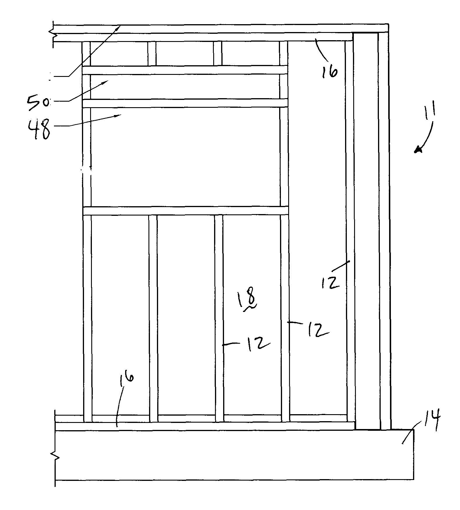
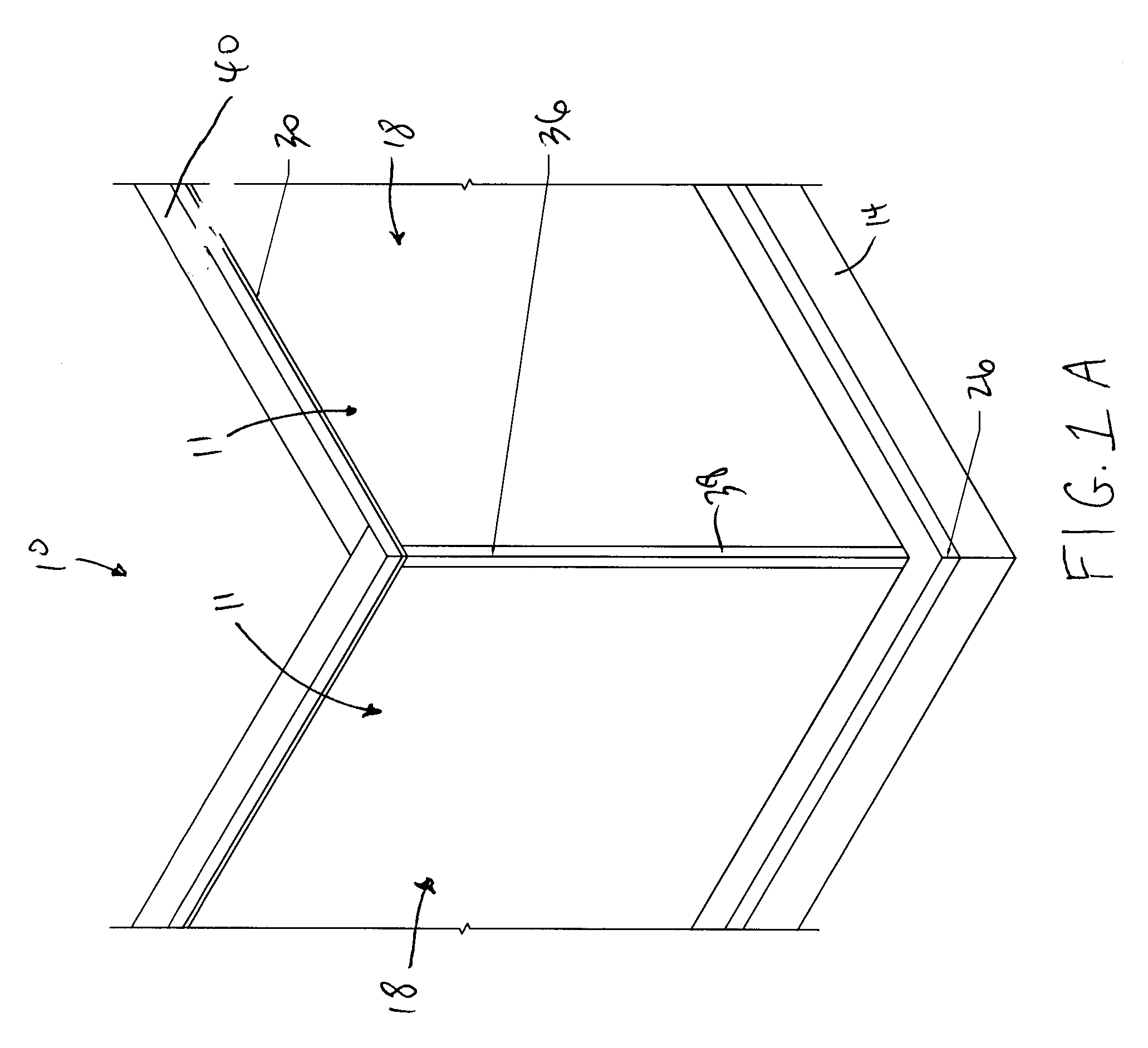
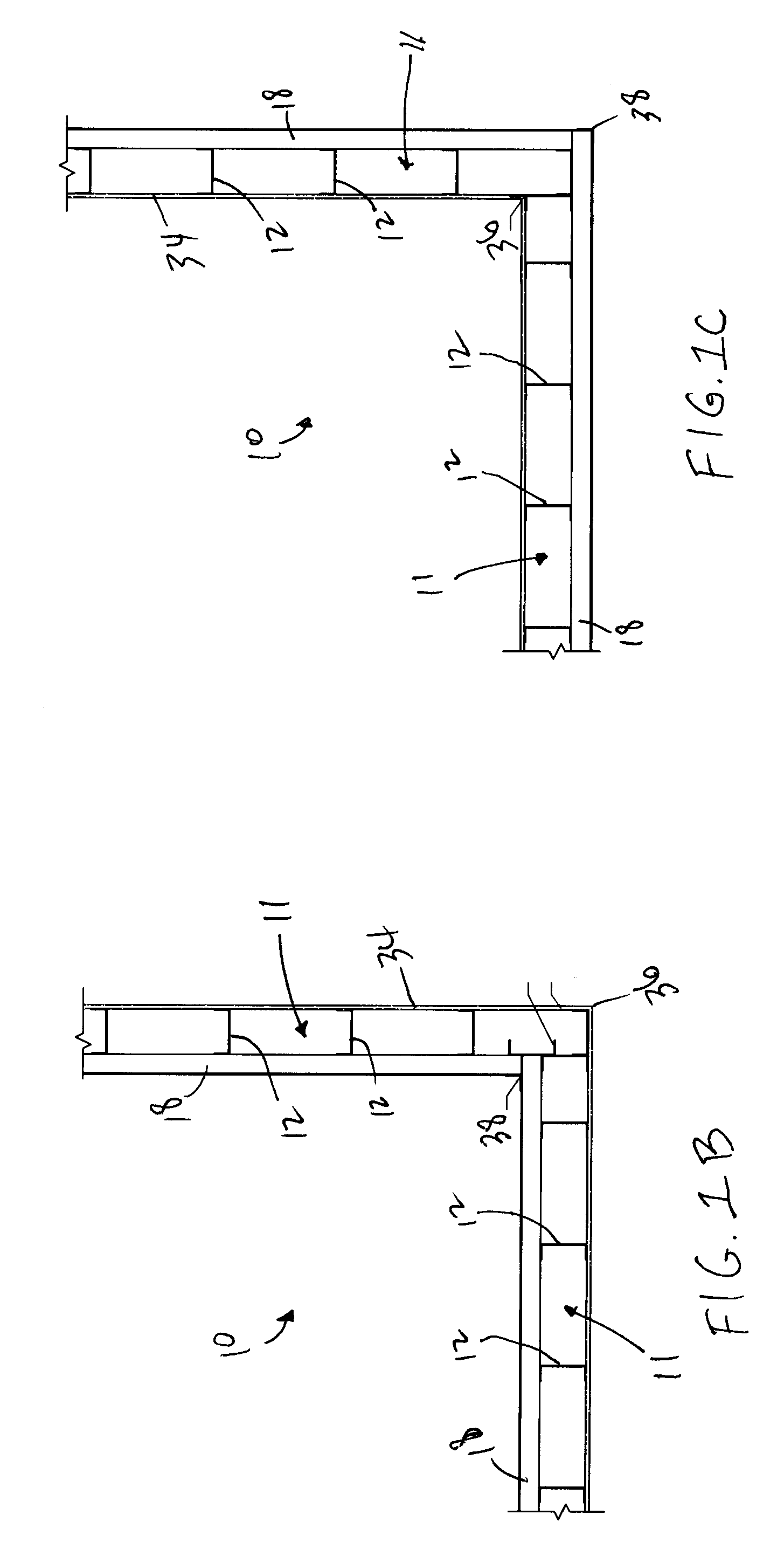
[0026]Referring to FIGS. 1A-1C, an exemplary embodiment of a wall system 10 is shown. Although the wall system 10 provided in the description below is in reference to the wall system being used in the basement of a house or dwelling, it should be understood by one of ordinary skill in the art that the wall system provided herein can be used as basement walls or any other structural walls of a building that are located below-grade.

[0027]The modular wall system 10 is formed of a plurality of wall sections 11, wherein each wall section 11 is pre-fabricated in a location away from the worksite and subsequently shipped to the worksite at which the plurality of wall sections 11 are joined together in an end-to-end manner at an angle to each other to enclose an interior space therewithin. Referring to FIGS. 1A-1C, an exemplary embodiment of a wall section of the modular wall system 10 is shown in the installed position along a concrete footer 14 that was previously installed at the worksit...


PUM

PropertyMeasurementUnit
heightaaaaaaaaaa
heightaaaaaaaaaa
widthaaaaaaaaaa

Abstract

A modular wall system for a building structure that includes a plurality of pre-fabricated wall sections that are attachable to each other to form the foundation for the building structure. Each wall section forms the entire length of a wall of the foundation. The wall sections include a plurality of steel studs having a track attached thereto at the top and bottom, at least one structural insulated panel attached to the studs, and at least one waterproofing sheet attached to the outer surface of the structural insulated panels to allow the wall sections to be used below-grade.

Description

FIELD OF THE INVENTION[0001]The present invention relates to a wall system for a building structure, and more particularly, a partially pre-fabricated wall system for use in a home or other building.BACKGROUND OF THE INVENTION[0002]One of the most demanding applications for building materials is use in foundation or basement walls. Such walls structures are subject to the weight of the building, as well as the weight of the surrounding ground, which exerts forces normal to the wall or wall panels. Besides the structural demands, such walls and the materials constituting them must be reasonably water-resistant, and preferably have a reasonably high insulating value (R-value).[0003]Standard residential and light commercial foundations are typically made of concrete-based products in a variety of different forms and embodiments. One embodiment is manufactured on the building site in the form of poured concrete. Another popular variation is pre-shaped and furnace-fired blocks (commonly ...

Claims


Application Information

Patent Timeline
Patent Type & Authority Applications(United States)
IPC IPC(8): E04B2/56E06B1/04E02D27/32E04B1/64E04C2/20
CPCE04B1/08E04B1/0007
Inventor KAPTEYN, PAUL
Owner KAPTEYN PAUL
Why Eureka
Try Eureka