Methods and systems for cooling in a vehicle

a technology for cooling components and vehicles, applied in the direction of machines/engines, propulsion parts, transportation items, etc., can solve the problem of reducing the space available for the additional airflow generation device, and achieve the effect of increasing airflow and decreasing airflow

Active Publication Date: 2012-12-20
GE GLOBAL SOURCING LLC
View PDF5 Cites 15 Cited by
  • Summary
  • Abstract
  • Description
  • Claims
  • Application Information

AI Technical Summary

Benefits of technology

[0005]In one embodiment, cooling of the component of the power dissipation system, such as one or more grids of resistive elements, may be used during dynamic braking operation of the vehicle during which engine load may be low, for example. In contrast, cooling of the component of the engine system, such as a heat exchanger, may be used during frill engine load conditions when a temperature of engine coolant may increase. Because cooling of the component of the power dissipation system and cooling of the component of the engine system may be performed at different times, a single airflow generating device may provide cooling to both the component of a power dissipation system and the component of an engine system, at least during selected operating conditions. Further, in another embodiment, a method may adjust the airflow generating device to increase airflow to one component while decreasing airflow to the other component depending on an operating condition to provide cooling where most effective. In still another embodiment, flow may be maintained to both components during some operating conditions, to thus provide cooling to the component of the power dissipation system and the component of the engine system simultaneously. As such, packaging space may be maintained as additional cooling of the component of the engine system may be carried out without adding an airflow generating device to the vehicle, although an additional airflow device may be used if desired.

Problems solved by technology

Further, during vehicle operation, various other engine components may require cooling.
In some vehicles, however, packaging constraints may reduce an amount of space available for the additional airflow generating device.

Method used


Image

  • Methods and systems for cooling in a vehicle
  • Methods and systems for cooling in a vehicle
  • Methods and systems for cooling in a vehicle

Examples


Embodiment Construction

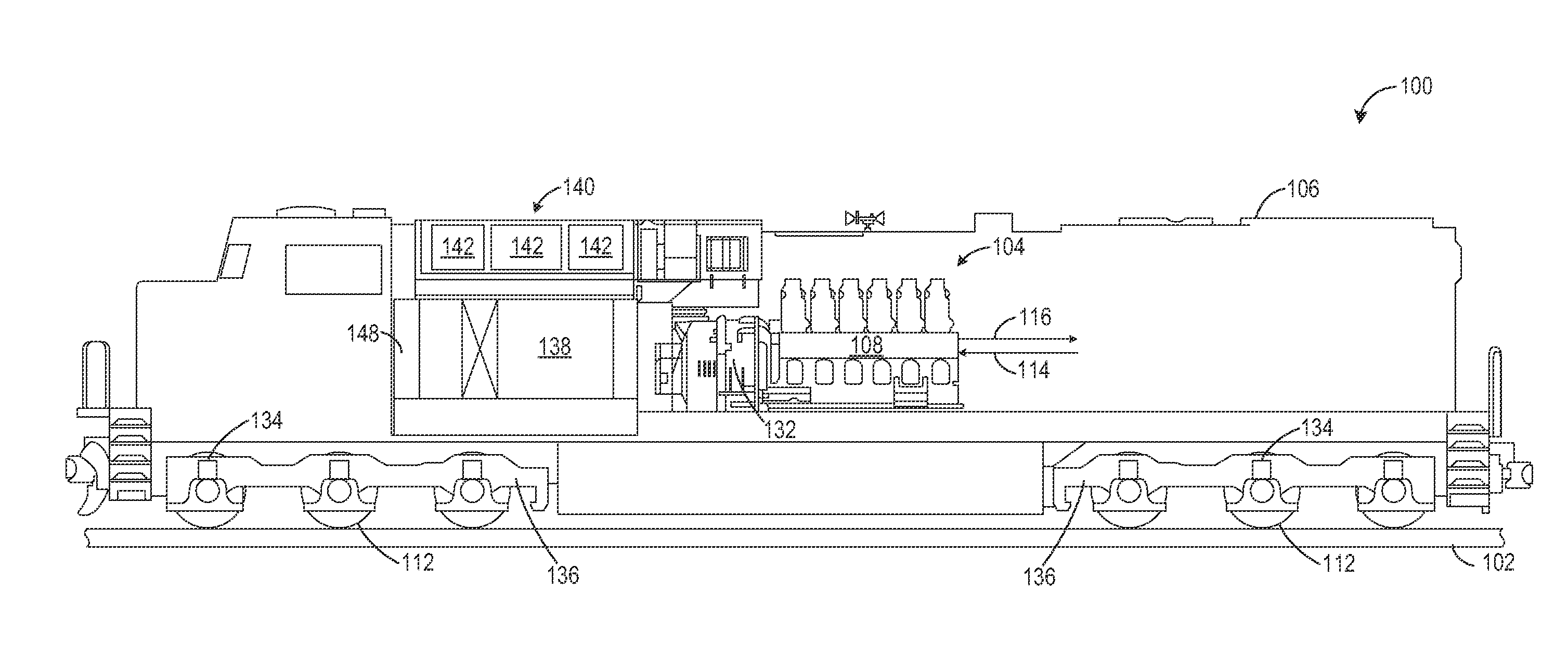
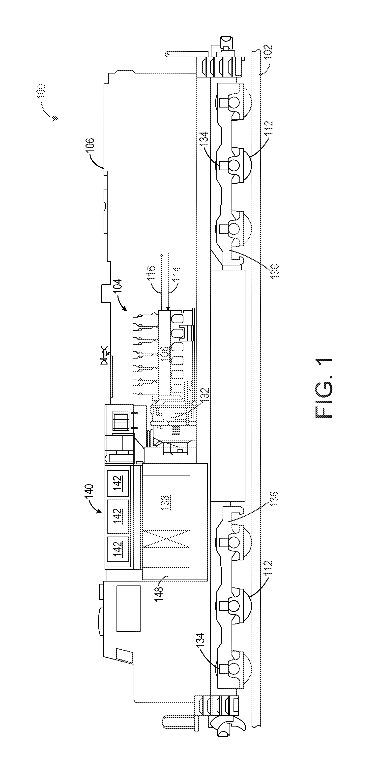
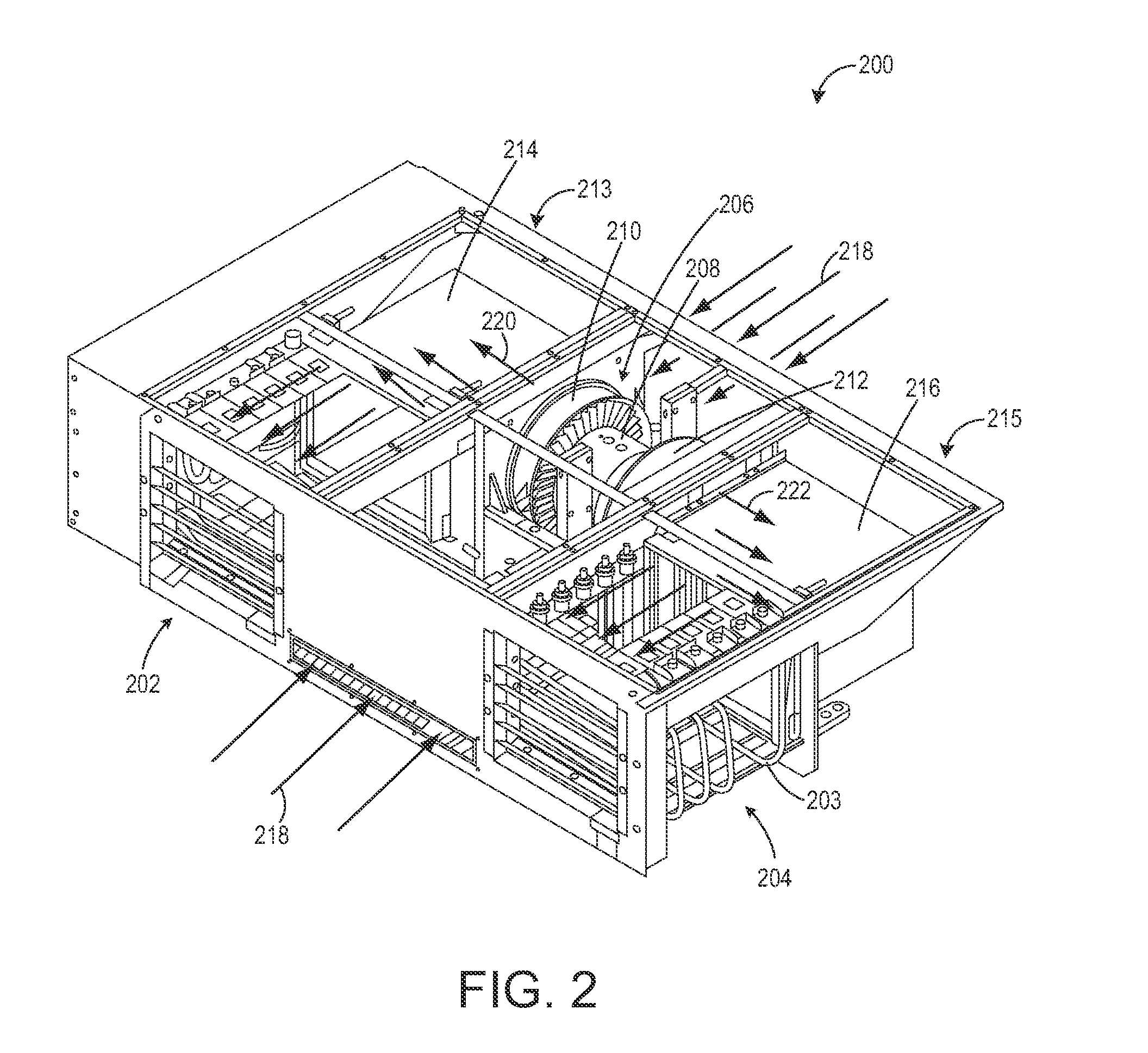
[0015]The following description relates to various embodiments of methods and system for a vehicle with an engine system and a power dissipation system. In one example embodiment, a method includes, directing airflow from an airflow generating device to cool a component of the power dissipation system, and directing the airflow from the airflow generating device to cool a component of the engine system. In such an embodiment, cooling may be provided to the component of the power dissipation system and the component of the engine system by a single airflow generating device, as cooling of each of the components may be desired at different times. As an example, cooling of the component of the power dissipation system may be desired during dynamic braking operation when the engine load is low and electrical energy is transferred to the power dissipation system. On the other hand, cooling of the component of the engine system may be desired when the engine load is high and a temperature...


PUM


Abstract

Various methods and systems are provided for a vehicle with an engine system and a power dissipation system. One example method includes, during directing airflow from an airflow generating device to cool a component of the power dissipation system, and directing the airflow from the airflow generating device to cool a component of the engine system.

Description

FIELD[0001]Embodiments of the subject matter disclosed herein relate to methods and systems for cooling various components in a vehicle including an internal combustion engine.BACKGROUND[0002]A propulsion system for a vehicle may include one or more traction motors to generate tractive output to propel and retard forward and reverse motion of the vehicle. In some examples, such as in a rail vehicle application, the traction motors may be used for dynamic braking in which the traction motors convert kinetic energy of the vehicle into electrical energy which is transmitted to one or more grids of resistive elements that dissipate the electrical energy in the form of heat. As such, an airflow generating device may be provided to cool the one or more grids of resistive elements during dynamic braking operation, as a temperature of the one or more grids of resistive elements increases during dynamic braking operation.[0003]Further, during vehicle operation, various other engine component...

Claims


Application Information

Patent Timeline
Patent Type & Authority Applications(United States)
IPC IPC(8): B61C5/02B60R99/00F01P1/00B61C17/00B60L7/00
CPCF01P1/06F01P2001/005B61C5/02B60L2200/26B60L7/02B60K2001/003B61C17/04Y10T137/6855
Inventor PTACEK, TODD ADAMLEUTE, SCOTTALLEN, PATRICK
Owner GE GLOBAL SOURCING LLC
Why Eureka
Try Eureka