
Drum

a technology of drums and drum bodies, applied in the field of drums, can solve the problems of affecting the operation of the drum unit, and affecting the operation of the drum unit, and achieve the effect of simplifying the handling of the tire body

Inactive Publication Date: 2012-12-20
HERBERT MASCHENBAU
View PDF3 Cites 14 Cited by
  • Summary
  • Abstract
  • Description
  • Claims
  • Application Information

AI Technical Summary

Benefits of technology

[0012]The telescopic guides can be formed respectively from at least two linear guides. Linear guides are comparatively simple to produce and are therefore available at a favourable cost. Also, linear guides, according to degree of overlap of guide elements, enable a transfer of comparatively high transverse forces. A linear guide can be constructed as a linear sliding guide of two guide elements or as a linear rolling guide with rolling bodies between two guide elements. As at least two linear guides are provided for the construction of the telescopic guides, the telescopic guide can also be constructed for example from three guide elements, which form two linear guides. The linear guide can be formed in the manner of a dovetail guide, rail guide or round bar guide. A telescoping capability of the linear guides or respectively of the guide elements can be achieved by a parallel offset arrangement of the guide elements relative to one another or a coaxial arrangement of the guide elements.
[0014]In order to obtain a comparatively wide drum unit having a great axial length, the drum can comprise a further second deflection device, which is spaced apart from the first deflection device. The axial movement of the actuation device can then be transferred via both deflection devices to the drum unit or respectively to the respective drum segments. Thus, it can be avoided that a jamming of the drum segments occurs due to one-sided loading of the drum unit, because an actuation force can be distributed by means of the two deflection devices relatively uniformly onto a length of the drum unit. Basically, it thus also becomes possible to construct comparatively wide tire bodies or to manufacture a plurality of tire bodies simultaneously with the drum. Depending on the case of application and the length of the drum unit, further deflection devices can also be provided.
[0015]The drum unit can comprise a set of outer drum segments and a set of inner drum segments, which in turn can be arranged respectively alternately over a periphery of the drum unit. A use of two types of drum segments makes it possible, with a contraction of the external diameter, to separate the respective drum segments from one another in a suitable manner.
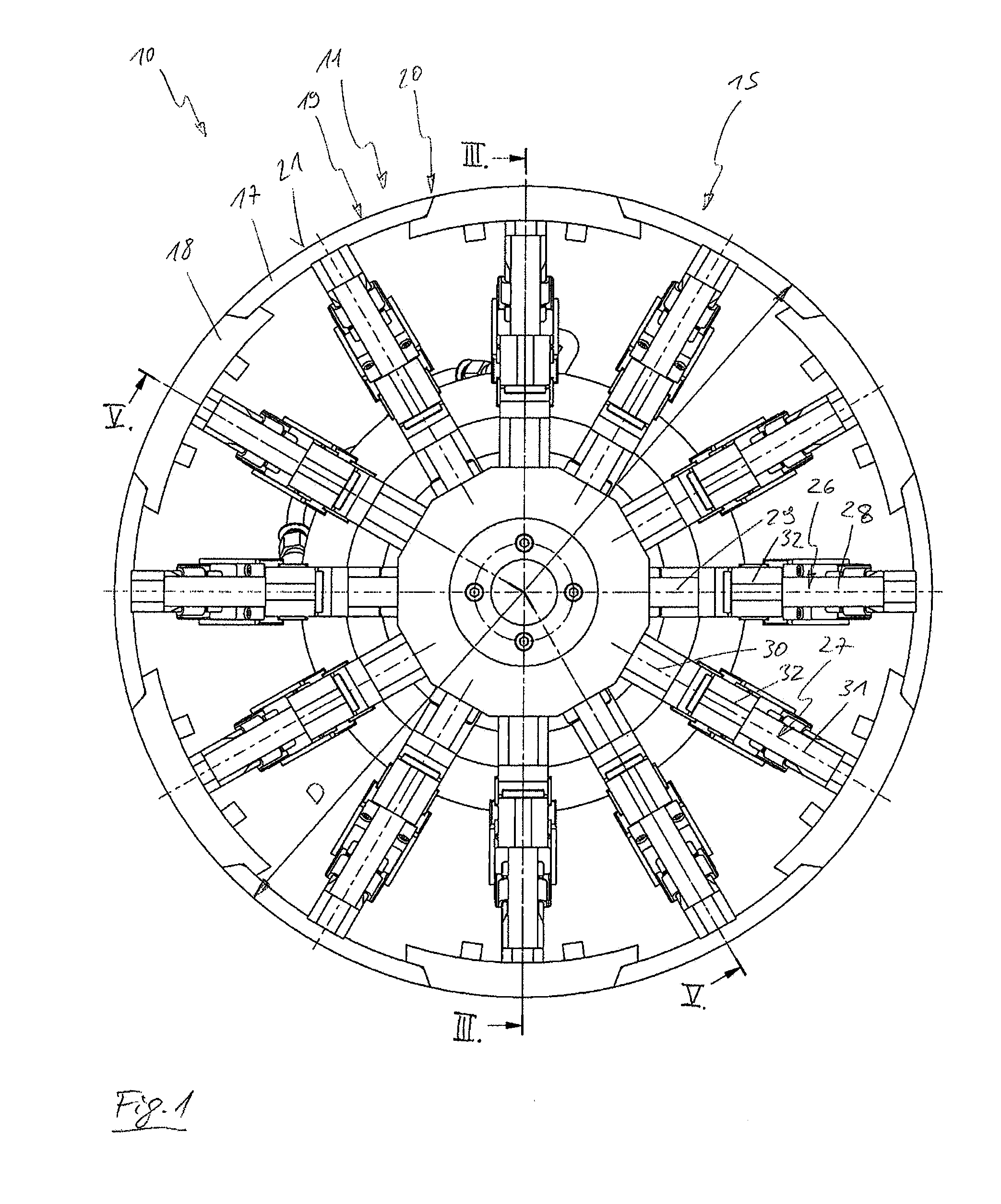
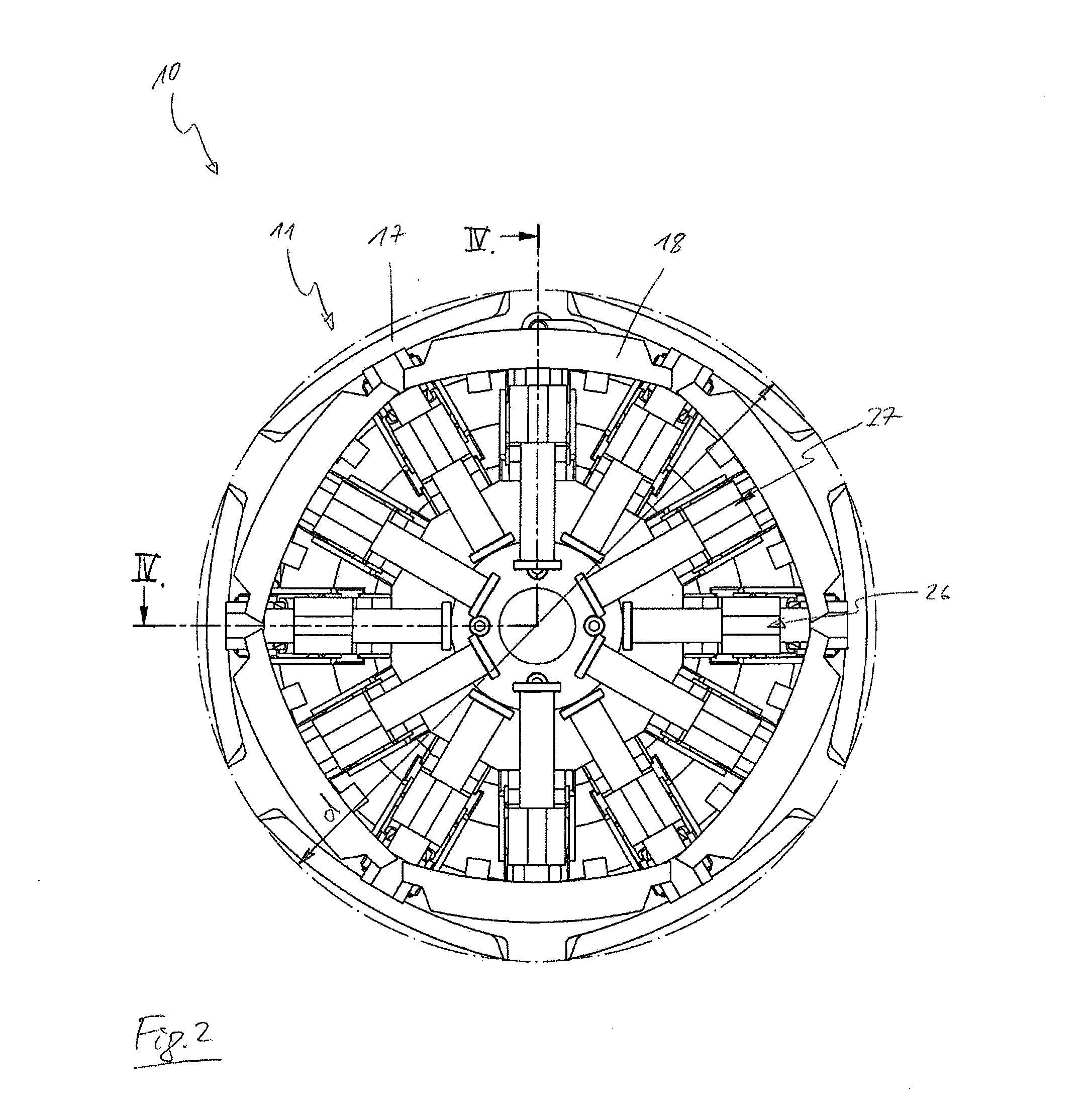
[0016]Thus, an external diameter D of the drum unit can be formed in an expanded position of the drum unit by all drum segments, and an external diameter d of the drum unit can be formed in a contracted position of the drum unit by solely the outer drum segments. Thus, it becomes possible that in the expanded position of the drum unit, a substantially closed circular cylinder can be formed from all drum segments. Gaps between the drum segments on the periphery of the drum unit, such as are known from clamping mandrels, can thus be avoided. A tire body can then be constructed in a particularly precise manner. When, in the contracted position, the outer drum segments form the external diameter d, the inner drum segments can be arranged inside the drum unit or respectively inside the circular cylinder which is thus formed. Thereby, it likewise becomes possible to reduce external diameter d in size as far as possible.
[0017]In this respect, it is advantageous if the telescopic guides for the inner drum segments have a greater guide length than the telescopic guides for the outer drum segments. The inner drum segments can then be moved further in radial direction than the outer drum segments. Also, via respectively different inclinations of the guide arrangements of the inner and outer drum segments, different movement lengths can be brought about with a movement of equal size of the actuation device.
[0020]In addition, the actuation device can have at least one fluid piston which is arranged concentrically on the drive shaft and is axially movable. Thereby, it becomes possible to move the conical rings in axial direction by means of the fluid piston. The fluid piston can be driven hydraulically or pneumatically. In addition, it is also conceivable to provide, instead of a fluid piston, an electromechanical linear drive or a drive which is not concentrically arranged on the drive shaft for the conical rings. A concentrically arranged fluid piston is, however, very compact and can generate great actuation forces.

Problems solved by technology

A disadvantage in the known drums is that they only permit a small, radial alteration of the external diameter of the drum unit.
Thereby, a removal or respectively stripping of a finished tire body from the drum unit is made difficult, because the tire body can only be moved within the play which is produced by the contraction of the external diameter.
In addition, an axial length of the drum unit is limited, so that only tire body with small widths can be manufactured.

Method used


Image

  • Drum
  • Drum
  • Drum

Examples


Embodiment Construction

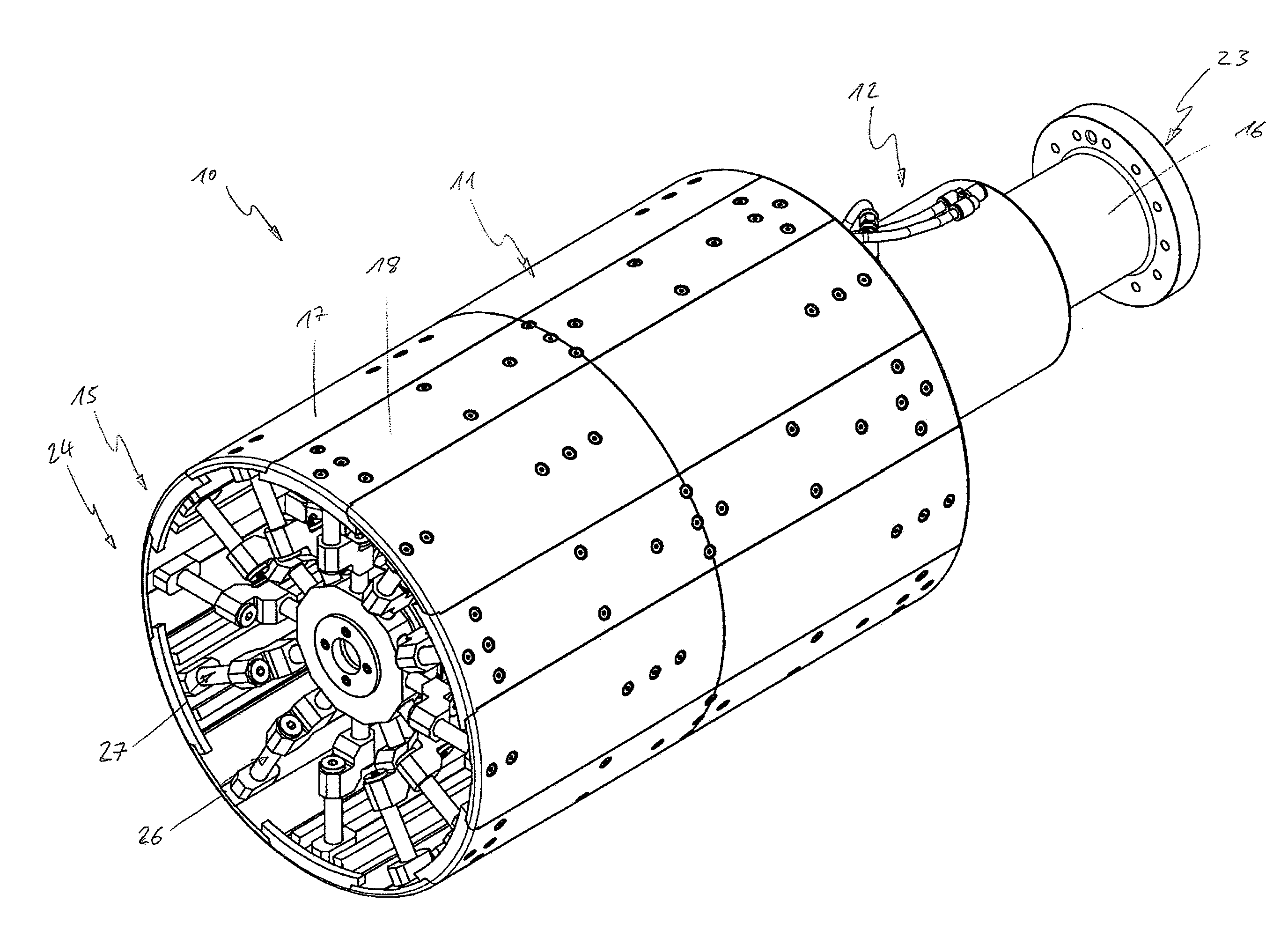
[0034]Viewing together FIGS. 1, 3 and 5 to 7 shows a drum 10 for clamping a tire body in an expanded position and FIGS. 2 and 4 show the drum 10 in a contracted position, in which the tire body, which is not illustrated here, can be removed from the drum 10. The drum 10 is formed substantially from a circular cylindrical drum unit 11, an actuation device 12 and deflection devices 13 and 14, and a holding device 15 on a drive shaft 16. The drum unit 11 is formed from circular-arc-shaped, outer drum segments 17 and inner drum segments 18, which are respectively arranged distributed alternately over a periphery 19 of the drum unit 11. The drum segments 17 and 18 are constructed here in a coinciding manner so that in connecting regions 20 of the drum segments 17 and 18, the latter overlap one another and a formation of gaps is avoided. In particular here the outer drum segments 17 project over the inner drum segments 18 on an outer side 21 of the drum unit 11. As can be seen from FIGS. ...


PUM

PropertyMeasurementUnit
Lengthaaaaaaaaaa
Diameteraaaaaaaaaa
Torqueaaaaaaaaaa

Abstract

A drum for the manufacture of a tire, in particular for winding or clamping a tire body, includes a circular cylindrical drum unit formed from circular-arc-shaped drum segments. The drum segments are movable in a radial direction, transversely to a rotation axis of the drum, such that an external diameter of the drum unit is changeable. The drum further includes an actuation device and a deflection device. The actuation device moves the drum segments. The deflection device has obliquely arranged telescopic guides that transfer an axial movement of the actuation device into a radial movement of the drum segments.

Description

CROSS REFERENCE TO RELATED APPLICATION[0001]The present application claims the benefit of German Patent Application No. 10 2011 077 569.2 filed Jun. 15, 2011, which is fully incorporated herein by reference.STATEMENT REGARDING FEDERALLY SPONSORED RESEARCH OR DEVELOPMENT[0002]Not applicable.FIELD OF THE INVENTION[0003]The invention relates to a drum for the manufacture of a tire, in particular for the winding or clamping of a tire body, wherein the drum comprises a circular cylindrical drum unit which is formed from circular-arc-shaped drum segments, wherein the drum segments are movable in a radial direction, transversely to a rotation axis of the drum, such that an external diameter of the drum unit is changeable, wherein the drum comprises an actuation device, by means of which the drum segments are movable, and wherein the drum comprises a deflection device.BACKGROUND OF THE INVENTION[0004]Such drums are sufficiently known from the prior art and serve substantially for the manufa...

Claims


Application Information

Patent Timeline
IPC IPC(8): B29D30/24
CPCB29D30/242
Inventor POPP, SEBASTIANGROSCH, DIETER
Owner HERBERT MASCHENBAU
Learn More