Surrounding area monitoring apparatus for vehicle

a technology for surrounding areas and monitoring apparatuses, applied in scene recognition, instruments, navigation instruments, etc., can solve the problems of individual emphasis on each target object, affecting the visibility of displayed images, and often not being equipped in a general type of vehicles

Inactive Publication Date: 2012-12-20
HONDA MOTOR CO LTD
View PDF64 Cites 47 Cited by
  • Summary
  • Abstract
  • Description
  • Claims
  • Application Information

AI Technical Summary

Benefits of technology

[0005]However, when there exist many target objects that are detected in the camera image, the individual emphasis on each target object could have adverse effect on the visibility of the displayed image. Therefore, the system has a room for improvement on the display image so that a driver could understand it more quickly.
[0010]In this aspect of the present invention, when detected target objects are relatively few, each target object are emphasized. In this case, the target objects are individually emphasized. On the other hand, when the detected target objects are relatively many, one emphasized indication is displayed for a whole display screen. Therefore, the displayed image may be more distinguishable and more understandable, compared with a image where all target objects are always emphasized individually regardless of the number of them. By only glancing at the one emphasized indication on the display, a driver can instantaneously understand that there exist many target objects around the vehicle, to which he should pay his attention. Thereby, the driver can concentrate on a driving operation without being disturbed by the displayed image.
[0016]In this embodiment, the display device of the car navigation system can be utilized efficiently to notify the driver of the presence of the target objects around the vehicle.

Problems solved by technology

However, when there exist many target objects that are detected in the camera image, the individual emphasis on each target object could have adverse effect on the visibility of the displayed image.
However, the HUD is often not equipped in an general type of vehicles.

Method used


Image

  • Surrounding area monitoring apparatus for vehicle
  • Surrounding area monitoring apparatus for vehicle
  • Surrounding area monitoring apparatus for vehicle

Examples


first embodiment

[0039]FIG. 3 is a flow chart showing a process to be executed by the image processing unit 2 according to a The process will be executed at predetermined intervals.

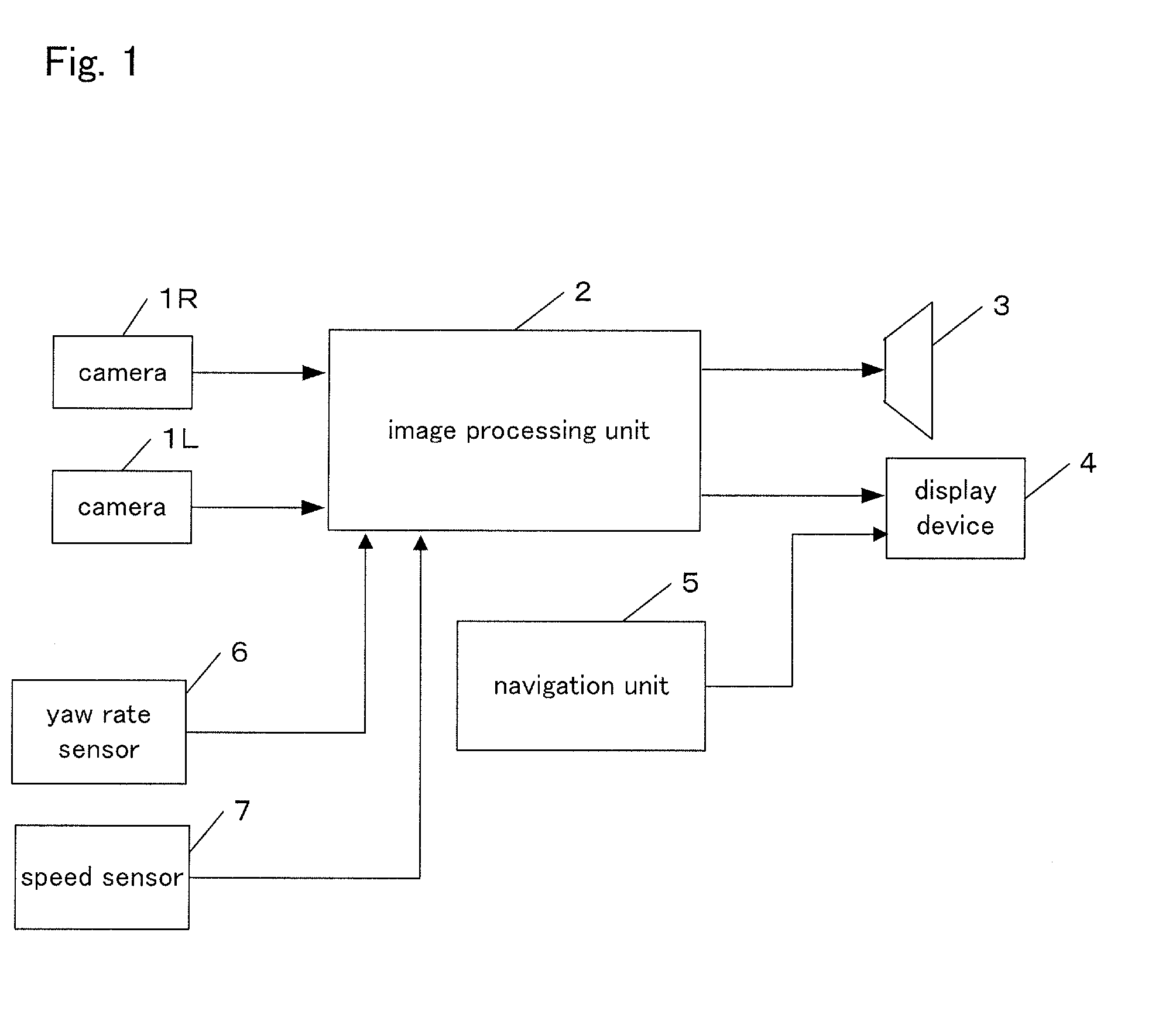
[0040]In steps S11 to S13, the image processing unit 2 performs A / D conversion of the input signals from the cameras 1R and 1L (i.e., data of captured image), and stores the converted signals in the image memory. The image data to be stored here is a grayscale image data containing intensity information.

[0041]In step S14, a right image captured by the camera 1R is used as a reference image (alternatively, a left image may be used as a reference image), and the reference image data are binarized. Specifically, data “1” (white) is set to a pixel having an intensity larger than a predetermined threshold level ITH, and data “0” (black) is set to a pixel having an intensity less than the predetermined threshold level ITH. The threshold level ITH can be determined by using any proper technique. After this binarization process,...

second embodiment

[0062]FIG. 8 shows a flow chart of a process to be executed by the image processing unit 2 according to the present invention. The process is executed at specified intervals.

[0063]Processes in steps S11 to S17 are the same as those in FIG. 3, so that descriptions for these processes are omitted for brevity's sake. In steps S18 to S28, a relative movement vector of a target object is calculated. The method of this calculation is detailed in JP 2001-6096 A, for example, so that it is only briefly described here.

[0064]In step S18, for each target objects extracted in S17, the center of gravity G and an area S, and an aspect ratio ASPECT of a circumscribed quadrangle (i.e., a rectangle circumscribed on the target object) is calculated. The area S is calculated by integrating all length of run length data for a corresponding target object. Coordinates of the center of gravity G are calculated as the crossing point of two lines bisectioning the area S in x direction and in y direction, re...


PUM


Abstract

A surrounding area of a vehicle is imaged, and target objects in the area are detected based on captured images. A driver is warned of the presence of the detected target objects by displaying a warning indication on the displayed image. If a total number of simultaneously detected target objects is equal to or less than a specified number, the warning indication of a first display mode is applied in which each target object is emphasized individually. If the total number is more than the specified number, the warning indication of a second warning display mode is applied in which one emphasized indication predefined is displayed for the whole displayed image without displaying the warning indication of the first display mode. The warning image becomes easier to understand for a driver, compared to an image where all detected objects are always emphasized individually regardless of the total number of them.

Description

FIELD OF THE INVENTION[0001]The present invention relates to an apparatus for monitoring a surrounding area around a vehicle, more particularly an apparatus for detecting and displaying target objects in the surrounding area.RELATED ART[0002]The following patent document 1 discloses a system that detects target objects around a vehicle, using an infrared camera. If the system determines the target object to be a pedestrian, a driver is notified of it with images and sounds.PRIOR ART DOCUMENT[0003]Patent Document 1: JP 2003-284057 ASUMMARY OF THE INVENTIONProblem to be Solved[0004]The system in the Patent Document 1 has a Head Up Display (HUD) mounted on the vehicle for displaying an image captured by the infrared camera. In order to notify of the presence of the target objects, the system emphasizes each image of the target object with a frame.[0005]However, when there exist many target objects that are detected in the camera image, the individual emphasis on each target object coul...

Claims


Application Information

Patent Timeline
Patent Type & Authority Applications(United States)
IPC IPC(8): H04N7/18
CPCB60R1/00B60R2300/106B60R2300/207B60R2300/307B60R2300/8093G01C21/3602G06K9/00805G08G1/166B60K2370/191G06V20/58
Inventor AIMURA, MAKOTONAKAMURA, YUSUKE
Owner HONDA MOTOR CO LTD
Why Eureka
Try Eureka