Target apparatus and isotope production systems and methods using the same

a technology of isotope production system and target apparatus, which is applied in the direction of isotope delivery system, electrical apparatus, chemical to radiation conversion, etc., can solve the problem of reducing the production of radioisotopes, and achieve the effect of reducing the pressure of vapor

Active Publication Date: 2012-12-20
GENERAL ELECTRIC CO
View PDF4 Cites 14 Cited by
  • Summary
  • Abstract
  • Description
  • Claims
  • Application Information

AI Technical Summary

Benefits of technology

The technical effect of this patent is related to how the size and shape of the chambers are designed to allow for optimal cooling of the air/vapor by allowing it to expand and become a liquid inside the device. Additionally, the inner surfaces of the chambers can also help with this process by being at lower temperatures compared to the outer surfaces of the channels where the air enters. This results in more efficient cooling and better conversion of the air into a liquid state.

Problems solved by technology

This patent discusses how systems for producing radioisotopes handle the issue of increased heat from the particles hitting the starting liquid in their targets. Conventional methods involve either reducing the beam current or adding a coolant like helium to prevent excessive evaporation of the liquid. These measures affect both the amount of radioisotopes produced and the overall efficiency of the system. Therefore, there is a technical problem of finding ways to manage this challenge while still optimizing the process of generating radioisotopes.

Method used


Image

  • Target apparatus and isotope production systems and methods using the same
  • Target apparatus and isotope production systems and methods using the same
  • Target apparatus and isotope production systems and methods using the same

Examples


Embodiment Construction

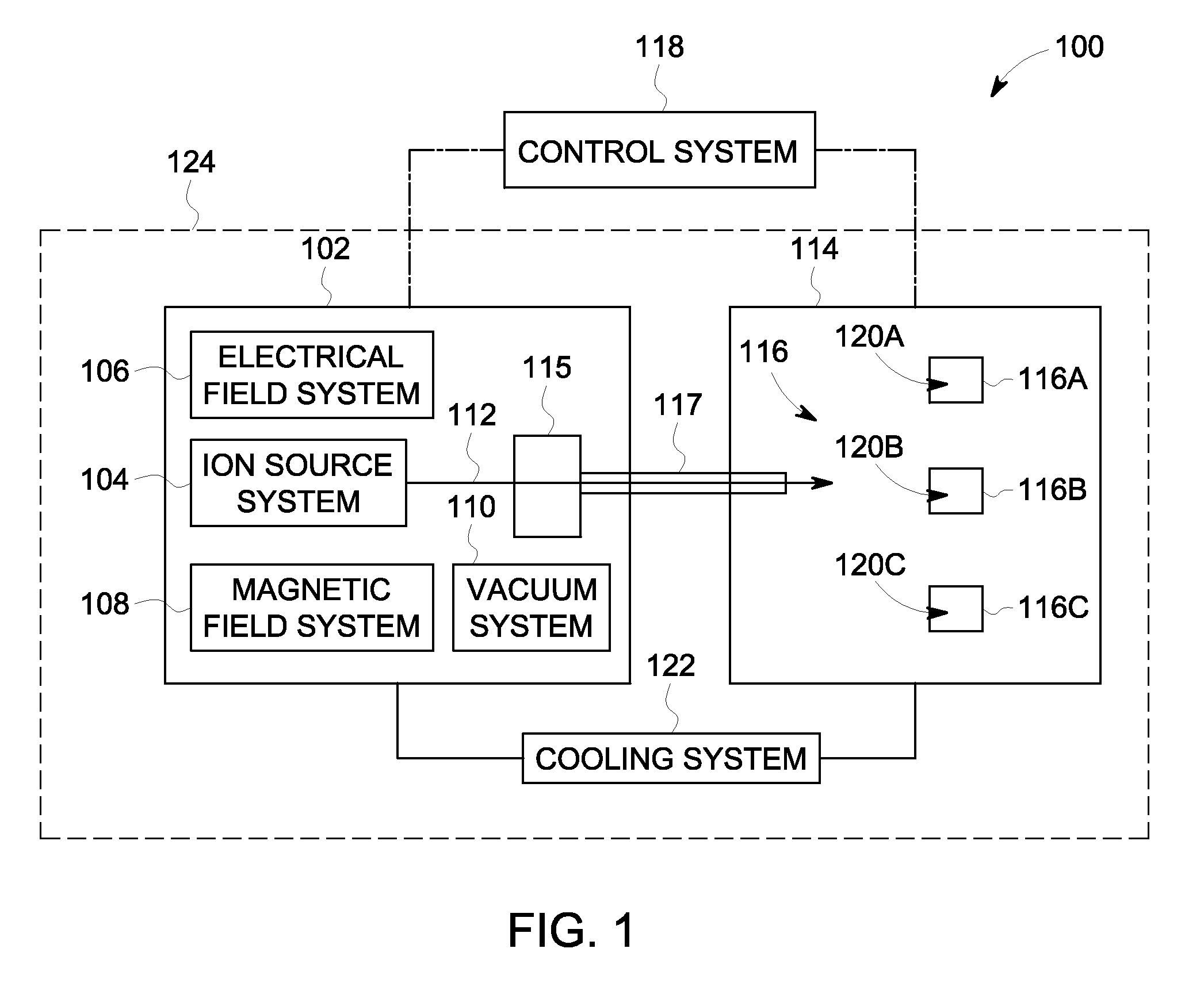
[0014]The foregoing summary, as well as the following detailed description of certain embodiments will be better understood when read in conjunction with the appended drawings. To the extent that the figures illustrate diagrams of the blocks of various embodiments, the blocks are not necessarily indicative of the division between hardware or structures. Thus, for example, one or more of the blocks may be implemented in a single piece of hardware or multiple pieces of hardware. It should be understood that the various embodiments are not limited to the arrangements and instrumentality shown in the drawings.

[0015]As used herein, an element or step recited in the singular and proceeded with the word “a” or “an” should be understood as not excluding plural of said elements or steps, unless such exclusion is explicitly stated, such as by stating “only a single” element or step. Furthermore, references to “one embodiment” are not intended to be interpreted as excluding the existence of ad...


PUM


Abstract

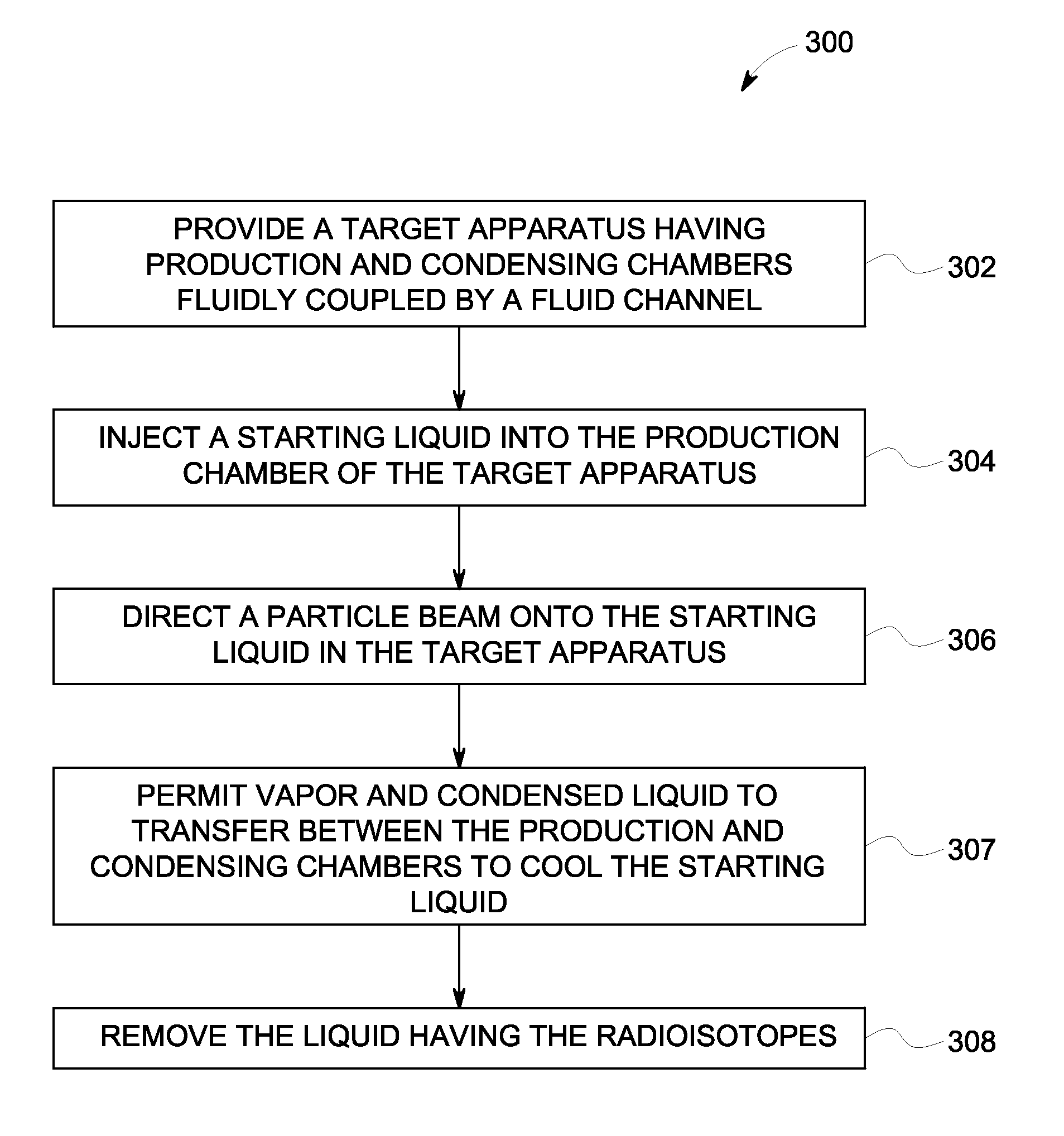
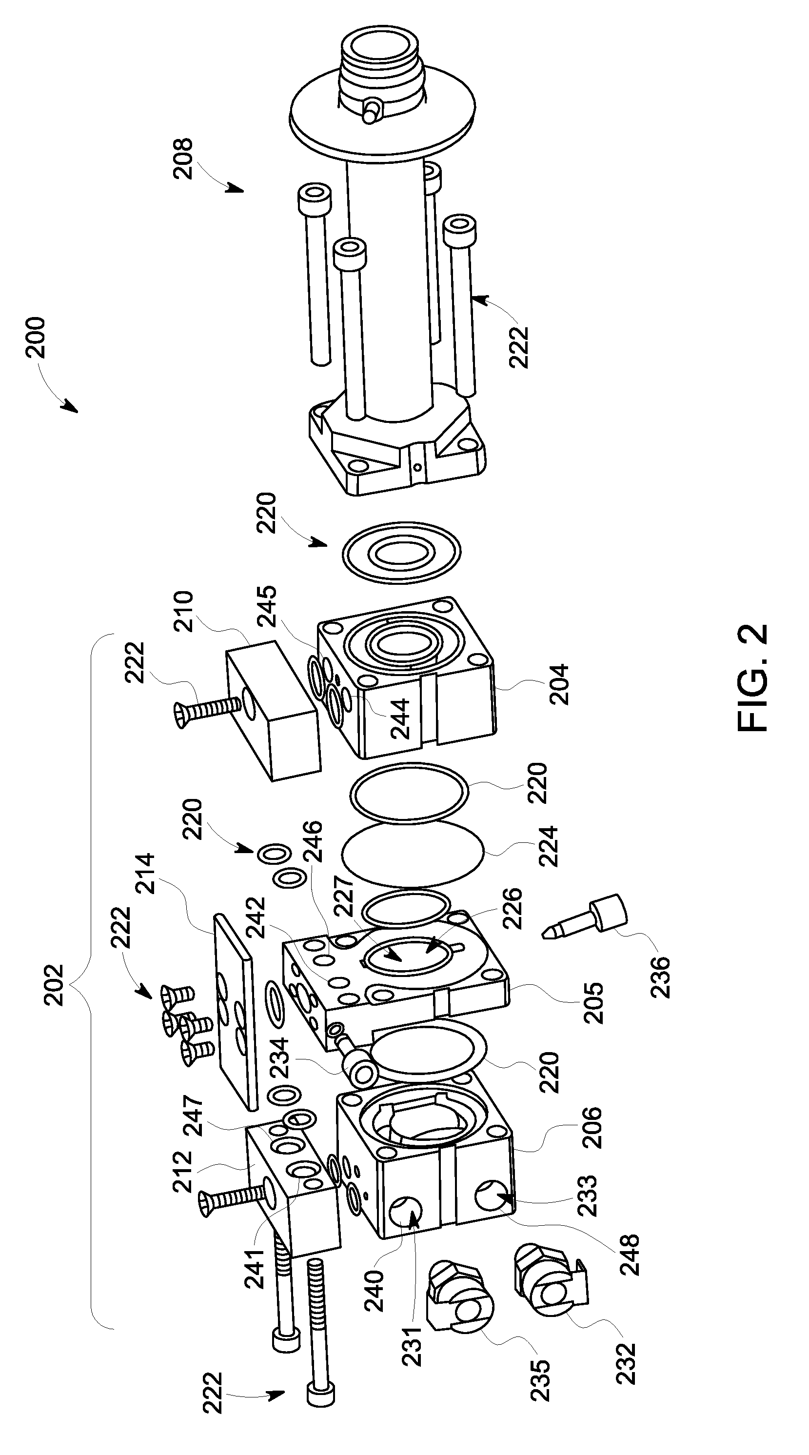
A target apparatus for a radioisotope production system. The target apparatus includes a production chamber that is configured to contain a starting liquid. The production chamber is configured to receive a particle beam that is incident upon the starting liquid thereby generating radioisotopes and transforming a portion of the starting liquid into vapor. The target apparatus also includes a condensing chamber and a fluid channel that fluidly couples the production and condensing chambers and is configured to allow the vapor to flow from the production chamber to the condensing chamber. The condensing chamber is configured to transform the vapor into a condensed liquid.

Description


Claims


Application Information

Patent Timeline
Owner GENERAL ELECTRIC CO
Why Eureka
Try Eureka