Electric storage element and production method thereof

a technology of storage elements and production methods, applied in the direction of electrolytic capacitors, cell components, cell component details, etc., can solve the problems of increasing production costs and increasing the number of components, and achieve the effect of ensuring air tightness

Active Publication Date: 2012-12-20
GS YUASA INT LTD
View PDF3 Cites 10 Cited by
  • Summary
  • Abstract
  • Description
  • Claims
  • Application Information

AI Technical Summary

Benefits of technology

[0022]According to the present invention, the external terminal is provided with the first shaft, which is fitted into the through hole in the casing and is welded thereto, so as to integrate the current collector with the casing. Therefore, it is possible to secure air tightness at the portion connected with the external terminal as well as achieve electrical connection between the current collector and the casing, with no need for any extra component.

Problems solved by technology

Such a configuration leads to increase of the number of components and complicated production steps, thereby resulting in increase of production costs.

Method used


Image

  • Electric storage element and production method thereof
  • Electric storage element and production method thereof
  • Electric storage element and production method thereof

Examples


Embodiment Construction

[0033]Hereinafter, an embodiment of the present invention will be described with reference to the accompanying drawings. In the following description, terms indicating specific directions and positions (including “above”, “below”, “side”, “end”, and the like) are used as necessary. These terms are used just for the purpose of easier understanding of the invention with reference to the drawings, and these terms should not restrict by their meanings the technical scope of the present invention. Moreover, the following description provides merely an essential example, and should not be intended to restrict the present invention, application targets, or usage thereof.

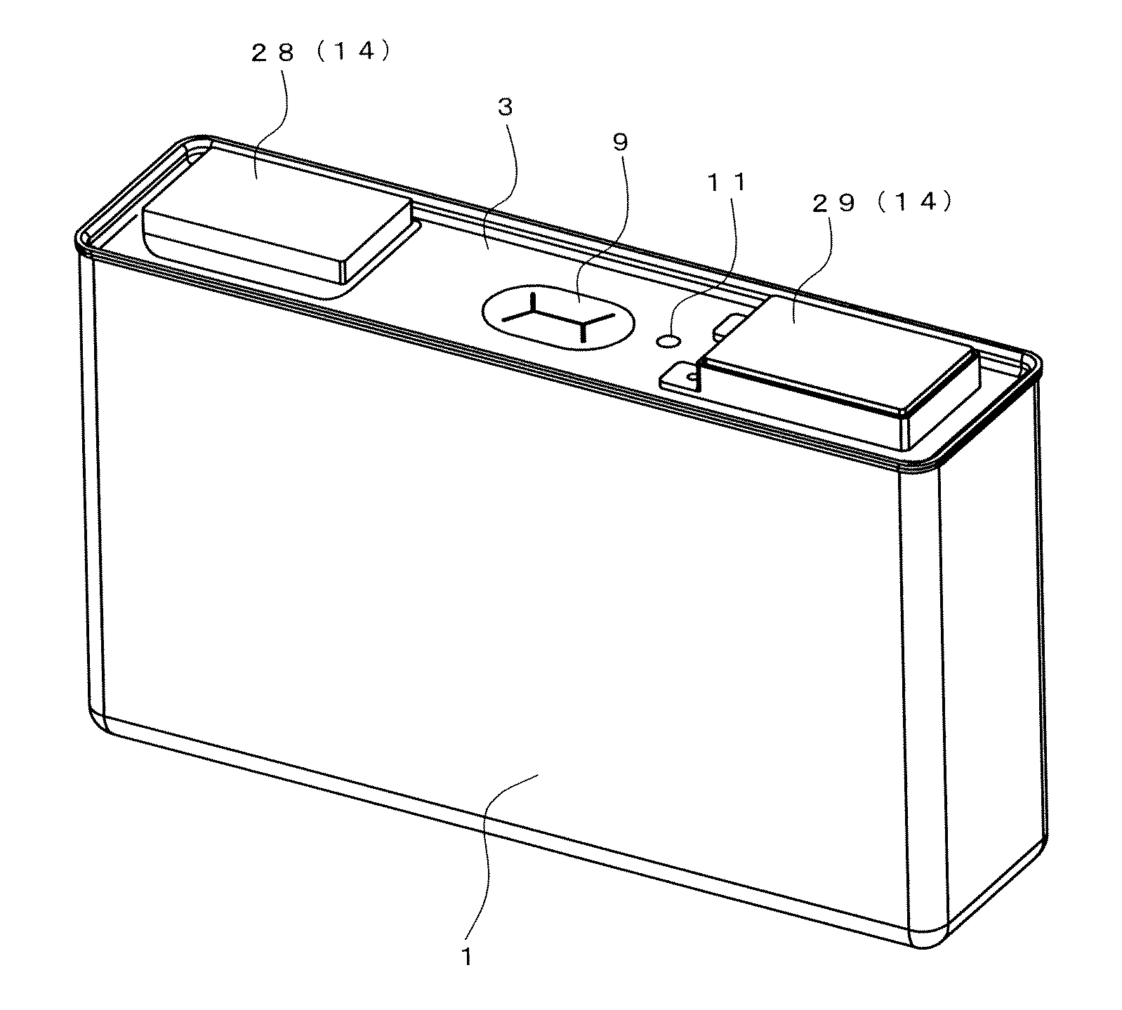
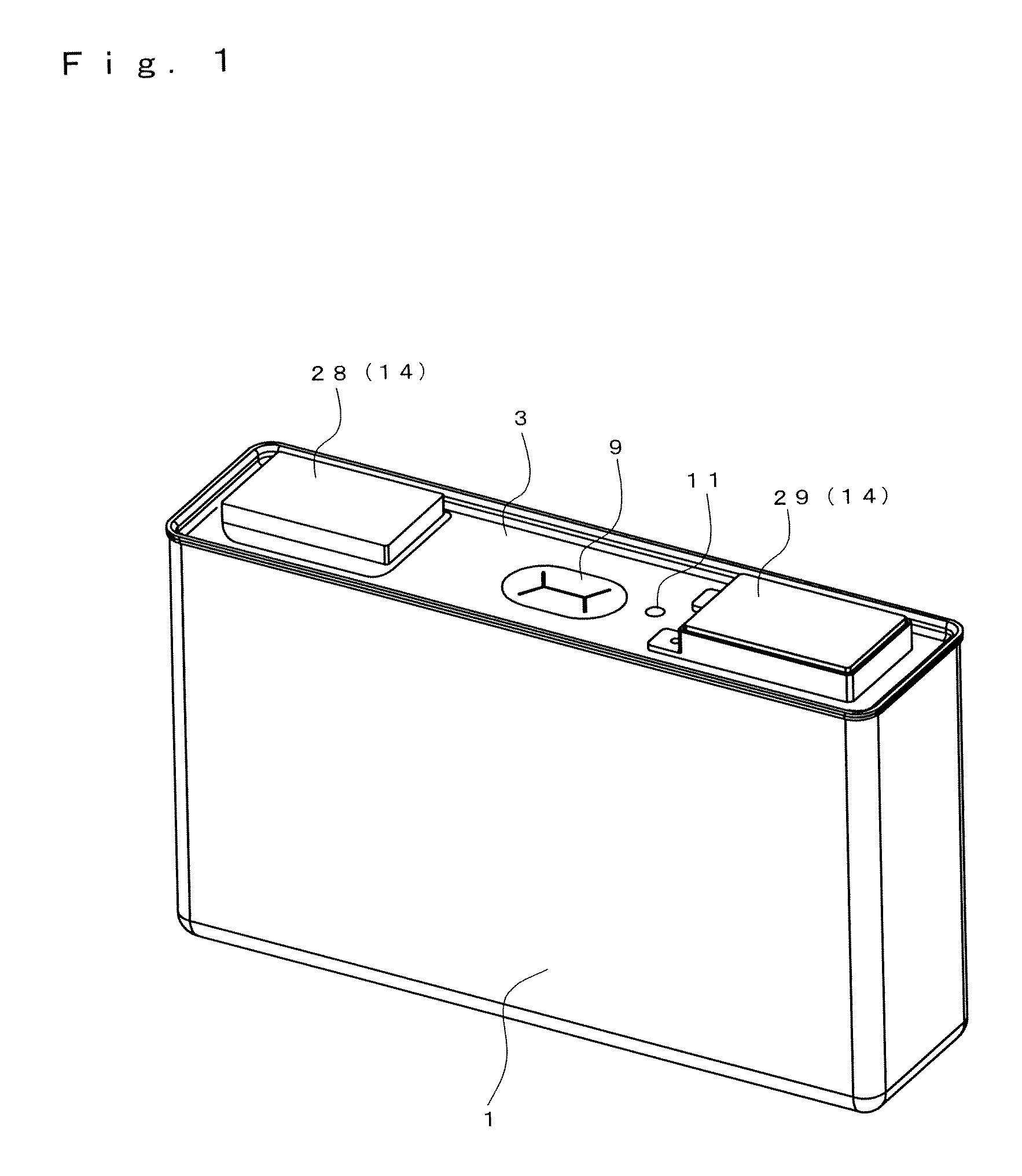
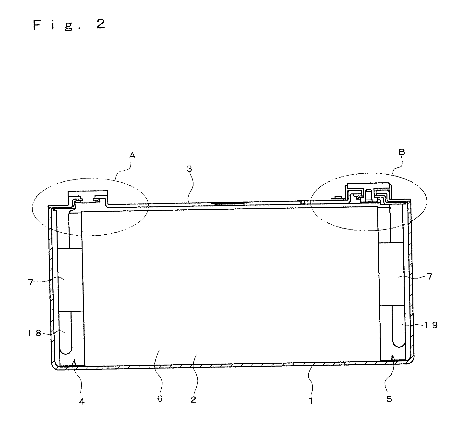
[0034]FIG. 1 shows a nonaqueous electrolyte secondary battery that exemplifies an electrochemical cell. As shown in FIG. 2, in the nonaqueous electrolyte secondary battery, a battery case 1 houses an electrode assembly 2 and is sealed with a cover 3. In this example, the battery case 1 and the cover 3 configure a casing.

[00...


PUM

PropertyMeasurementUnit
diameteraaaaaaaaaa
heightaaaaaaaaaa
strengthaaaaaaaaaa

Abstract

There is provided an electric storage element and a production method thereof. The electric storage element has excellent air tightness at a portion connected with an external terminal and realizes high assembling performance, even in a simple configuration. The electric storage element includes casings, an external terminal that has a surface exposed outward from one of the casings, a current collector that is provided inside the casings and is connected to the external terminal, and an electrode assembly that is provided inside the casings and is connected to the current collector. The casings are provided with a through hole. The external terminal includes a flange in contact with an outer surface of one of the casings, and a first shaft that extends from the flange to be inserted into the through hole in one of the casings and be welded over the entire periphery.

Description

CROSS-REFERENCE TO RELATED APPLICATIONS[0001]This application claims priority from Japanese Patent Application Nos. 2011-135166 and 2012-111398, the disclosure of which are incorporated herein by reference in their entireties.BACKGROUND OF THE INVENTION[0002]1. Field of the Invention[0003]The present invention relates to an electric storage element and a production method thereof.[0004]2. Description of the Related Art[0005]JP 2009-087727 A and JP 2009-087728 A each disclose a conventional battery configured such that each of a body and a distal end of a shaft of an external terminal is sequentially inserted into a through hole provided in a cover and a shaft through hole provided in an insulator with a gasket being interposed therebetween, and is then inserted into a shaft through hole provided in a first plate, and thereafter the distal end of the shaft is caulked, so that the cover, the insulator, and the first plate are held and integrated by the external terminal.[0006]Furtherm...

Claims


Application Information

Patent Timeline
Patent Type & Authority Applications(United States)
IPC IPC(8): H01M2/02H05K13/00H01G9/08H01M2/30H01M50/176H01M50/528H01M50/55H01M50/553H01M50/562H01M50/566
CPCH01M2/06H01M2/30Y10T29/49117Y02E60/10H01M50/562H01M50/55H01M50/553H01M50/176H01M50/566H01M50/543H01M50/147
Inventor ITO, SYUN
Owner GS YUASA INT LTD
Why Eureka
Try Eureka