Turbo compressor and refrigerator

a compressor and refrigerator technology, applied in the field of refrigerators and compressors, can solve the problems of reduced oil in the oil tank, reduced volumetric efficiency, rise in the storage temperature of compressors, etc., and achieve the effect of suppressing backflow and simple configuration

Active Publication Date: 2016-08-16
DAIKIN IND LTD
View PDF11 Cites 1 Cited by
  • Summary
  • Abstract
  • Description
  • Claims
  • Application Information

AI Technical Summary

Benefits of technology

[0009]The present invention provides a turbo compressor and a refrigerator which can suitably suppress the back flow of the refrigerant through the pressure equalization pipe to the oil tank side by means of a simple configuration.
[0015]In the turbo compressor, since the check valve does not protrude outside the case, it is possible to secure the air-tightness of the overall case and promote the space saving of the overall compressor.
[0018]According to the present invention, it is possible to suitably suppress the back flow of the refrigerant through the pressure equalization pipe to the oil tank side by means of a simple configuration.

Problems solved by technology

In the compressor, if the compression ratio increases, the discharging temperature of the compressor rises and the volumetric efficiency declines.
There is a problem that the refrigerant flows backward to the oil tank and leaks from a labyrinth seal into a compressor flow path or a motor, and, at this time, the lubricant oil, which is being refueled to the bearing near the labyrinth, is also taken out as oil leakage, whereby the amount of oil in the oil tank is reduced.

Method used


Image

  • Turbo compressor and refrigerator
  • Turbo compressor and refrigerator
  • Turbo compressor and refrigerator

Examples


Embodiment Construction

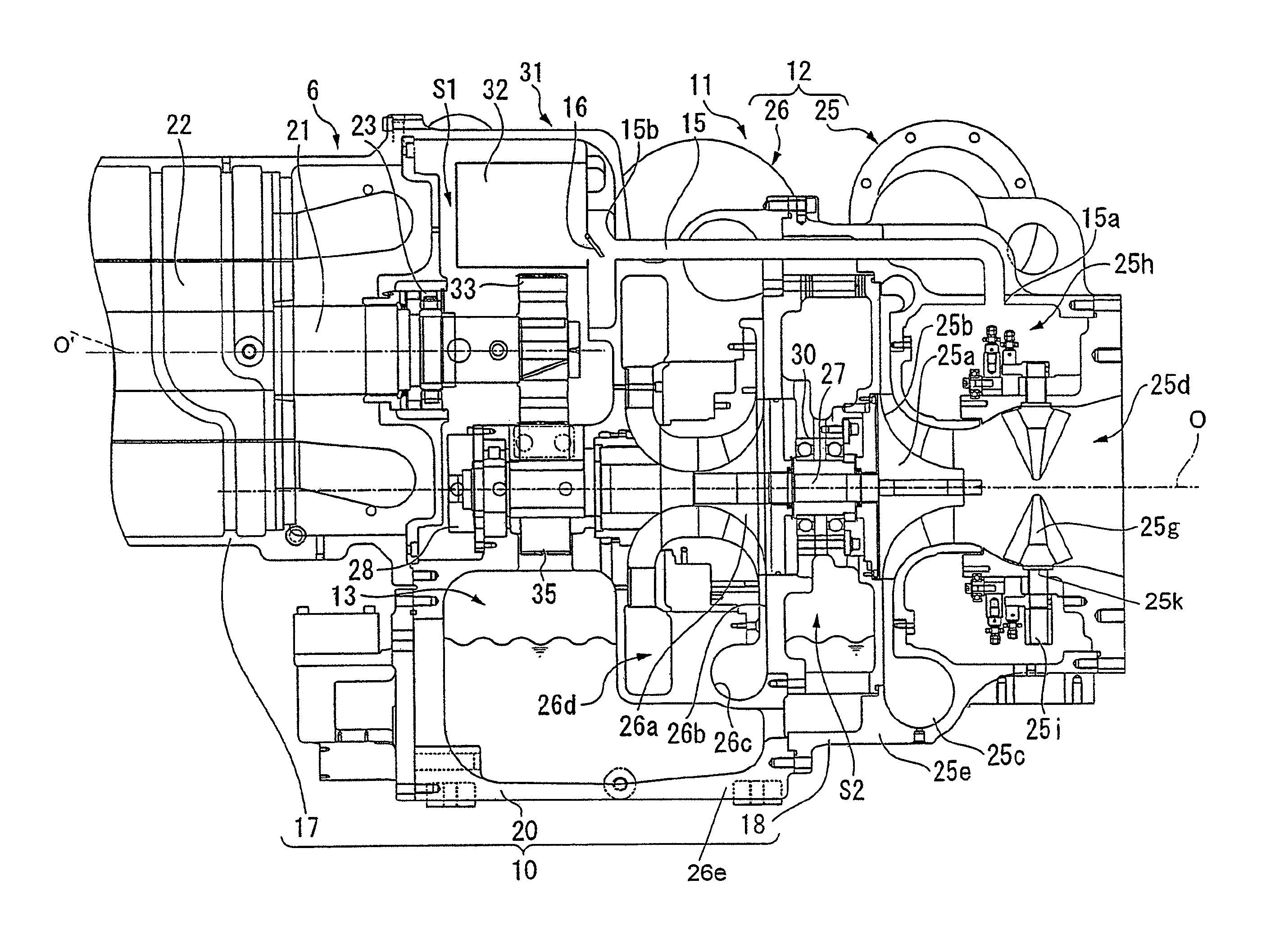
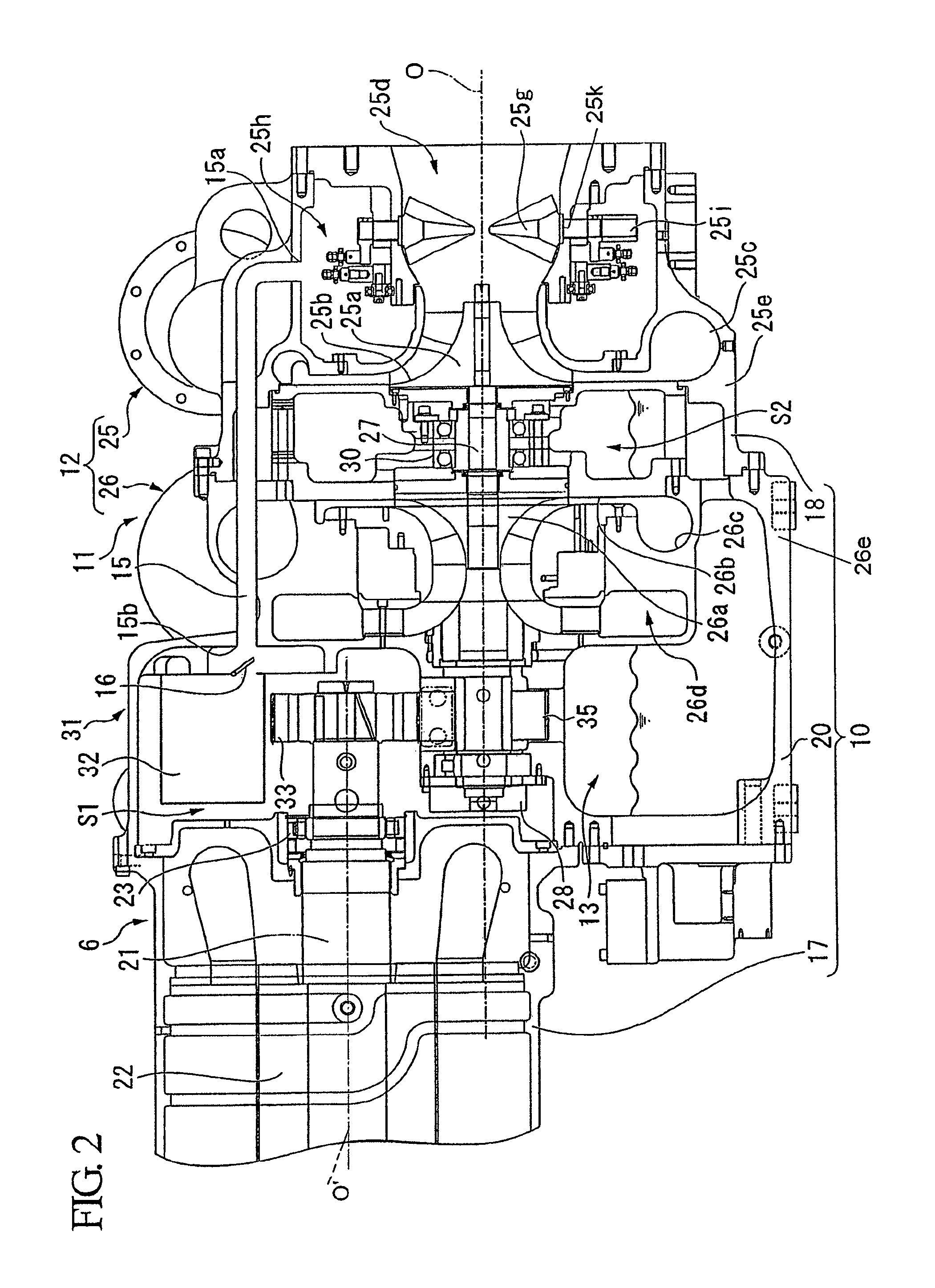
[0022]An embodiment of a turbo compressor and a refrigerator relating to the present invention will be described with reference to FIGS. 1 and 2.

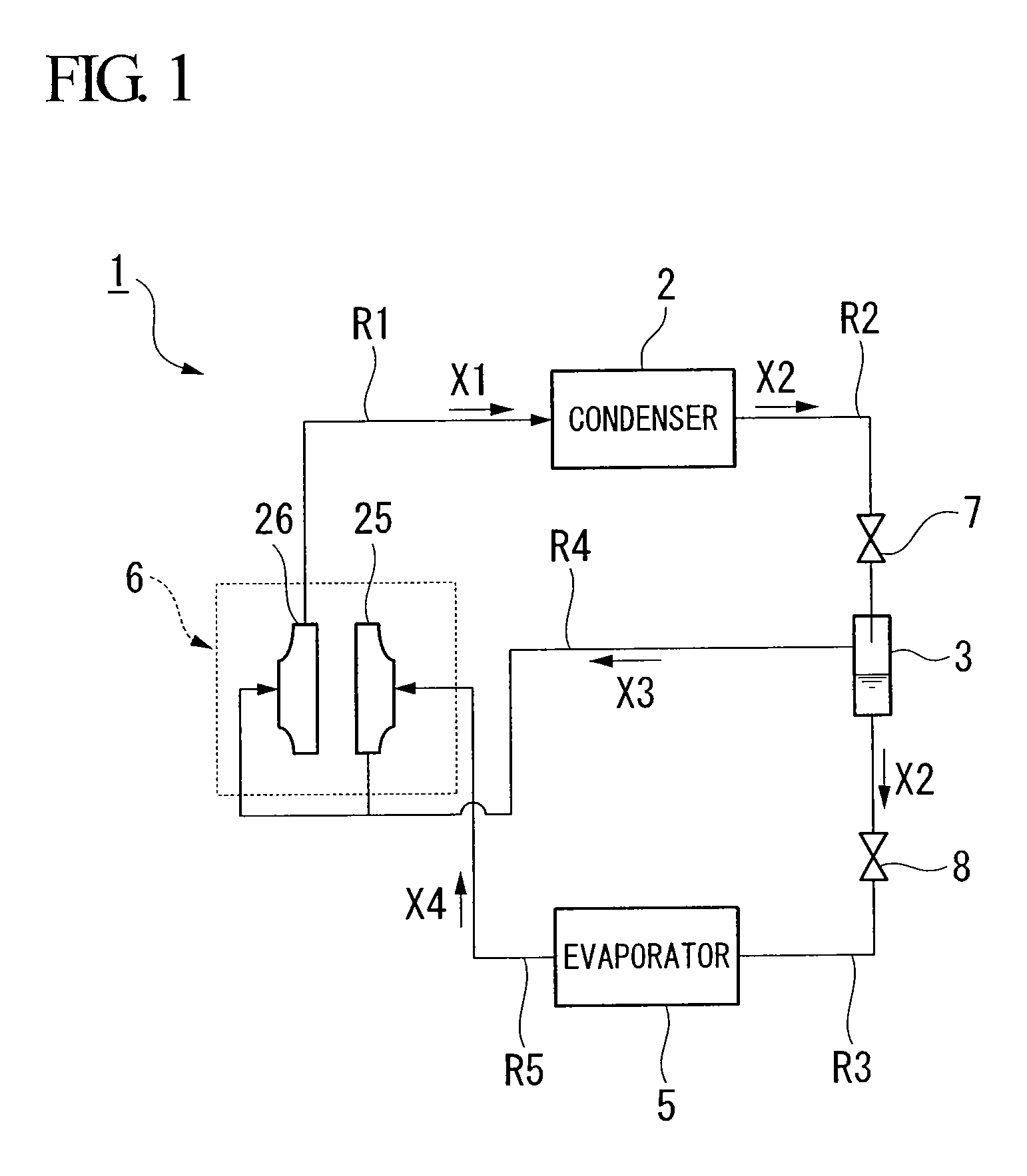
[0023]A turbo refrigerator (a refrigerator) 1 relating to the present embodiment is, for example, installed on a building or a factory so as to create the cooling water for air conditioning. As shown in FIG. 1, the turbo refrigerator 1 includes a condenser 2, an economizer 3, an evaporator 5 and a turbo compressor 6.

[0024]The condenser 2 is supplied with a compressed refrigerant gas X1, which is a refrigerant (a fluid) compressed in a gas state, and makes the compressed refrigerant gas X1 a refrigerant liquid X2 by cooling and liquefying the compressed refrigerant gas X1. As shown in FIG. 1, the condenser 2 is connected to the turbo compressor 6 via a flow path R1 through which the compressed refrigerant gas X1 flows and is connected to the economizer 3 via a flow path R2 through which the refrigerant liquid X2 flows. An expansion valve 7 f...


PUM


Abstract

A turbo compressor includes a case; compression stages which are disposed in a plural number in a rotatable manner with respect to the case via a sliding part; an oil tank in which a lubricant oil to be supplied to the sliding part is stored; a pressure equalization pipe which communicates the oil tank with the vicinity of the inlet of the compression stage; and a check valve which allows only the movement of the fluid from the oil tank side to the compression stage side in the pressure equalization pipe.

Description

BACKGROUND OF THE INVENTION[0001]1. Field of the Invention[0002]The present invention relates to a turbo compressor and a refrigerator. More specifically, the present invention relates to a turbo compressor capable of compressing a fluid by a plurality of impellers and a refrigerator including the turbo compressor.[0003]Priority is claimed on Japanese Patent Application No. 2009-170193, filed Jul. 21, 2009, the content of which is incorporated herein by reference.[0004]2. Description of Related Art[0005]There is known a turbo refrigerator or the like including a turbo compressor which compresses and discharges the refrigerant by means of a compressing means equipped with an impeller or the like as a refrigerator for cooling or refrigerating a material to be cooled such as water.[0006]In the compressor, if the compression ratio increases, the discharging temperature of the compressor rises and the volumetric efficiency declines. Thus, in the turbo compressor included in the turbo ref...

Claims


Application Information

Patent Timeline
Patent Type & Authority Patents(United States)
IPC IPC(8): F25B43/02F04D25/02F04D17/12F04D29/58F04D29/063
CPCF04D17/12F04D25/02F04D29/063F04D29/5826F04D29/584
Inventor ODA, KENTAROUTSUKAMOTO, MINORU
Owner DAIKIN IND LTD
Why Eureka
Try Eureka