Airtight cap structure

a technology of airtight caps and caps, applied in the direction of caps, packaging goods, packaging foodstuffs, etc., can solve the problem and achieve the effect of increasing the number of parts required

Inactive Publication Date: 2010-05-04
KOTOBUKI & CO LTD
View PDF10 Cites 8 Cited by
  • Summary
  • Abstract
  • Description
  • Claims
  • Application Information

AI Technical Summary

Benefits of technology

[0006]The present invention has been made in view of the above described problems, and an object of the invention is to provide an airtight cap structure capable of having a design property and securing air-tightness without increasing the number of parts.
[0014]Both the cap and the vicinity of the use end portion of the main body can be respectively configured by two color molding of the soft portion and the hard portion, and the soft portions of both of them are mutually bought into contact with each other so as to secure air-tightness. Thus, both of them can be closely contacted, and it is possible to secure air-tightness of the use end portion more reliably.

Problems solved by technology

Nevertheless, there is a problem in that the number of parts required is increased.

Method used


Image

  • Airtight cap structure
  • Airtight cap structure
  • Airtight cap structure

Examples


first embodiment

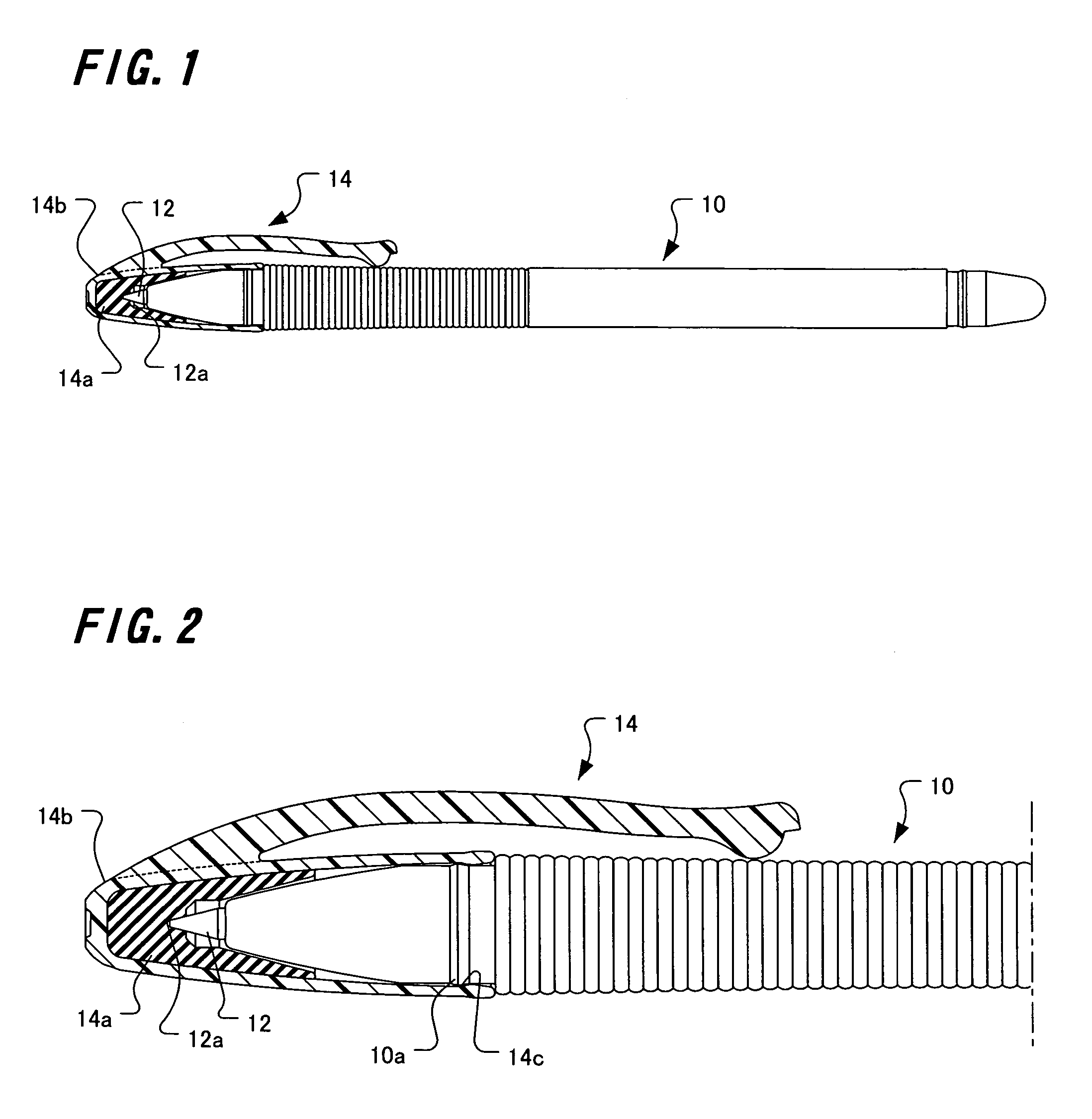
[0031]FIGS. 1 and 2 are views showing an example of adapting an airtight cap structure according to the present invention to a writing tool. In the Figures, the writing tool includes a main body 10, and the main body 10 has a refill 12 as a writing body in its interior. In the tip end portion of the main body 10, a use end portion 12a of the tip end of the refill 12 is exposed.

[0032]When the refill 12 is not used, a cap 14 covers the use end portion 12a and the tip end of the main body 10 in order to prevent drying out of the use end portion 12a so as to protect the use end portion 12a.

[0033]The cap 14 is configured by two-color injection molding of a soft portion 14a comprised of an elastic soft resin and a hard portion 14b comprised of a hard resin. In this example, the soft portion 14a configures only one portion of the internal surface portion of the cap 14, and the hard portion 14b configures the other portion of the cap 14 including a grip portion.

[0034]The internal surface i...

second embodiment

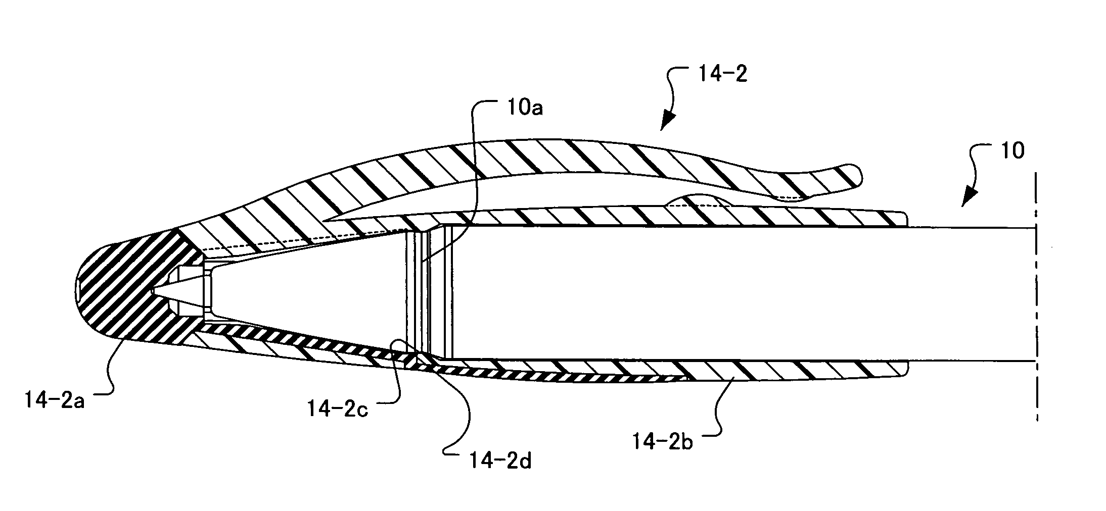
[0047]In the cap structure configured as describe above, similarly to the second embodiment, when the use end portion 12a is not used and the cap 14-2 is attached to it, the engaging protrusion 14-2c of the hard portion 14-2b is engaged with the engaging portion 10a and the attaching state can be maintained. In this state, since the use end portion 12a is inserted into the soft portion 14-2a configuring the top portion of the cap 14-2 to make a direct contact to be sealed, air-tightness of a refill 12 can be secured.

[0048]The soft portion 14-2a is exposed to the outside of the cap 14-2 so as to configure the external appearance of the cap 14-2, and in particular, the soft portion 14-2a is exposedly arranged so as to be separated into the top portion and the portion of the external peripheral surface in the outside of the cap 14-2, and appropriately setting a shape and a color of this exposed portion of the soft portion 14-2a broaden the freedom of the width of the design, and the de...

sixth embodiment

[0057]FIG. 11 is a whole view of a writing tool adapting an airtight cap structure according to the present invention, and FIG. 12 is an enlarged vertical longitudinal view of the main part.

[0058]In the figures, this writing tool generally has a main body 30, a cap 34, and an operating portion 36. The main body 30 has a refill 32 as a writing body in its interior, and in the tip end of the main body 30, a use end portion 32a of the tip end of a refill 32 is exposed. The operating portion 36 and the cap 34 are connected through a rotation converting mechanism, and when the operation portion 36 is knocked, the cap 34 advances, and after that, the cap 34 rotates around an axis parallel to the longitudinal direction of the main body 30, and then, the cap 34 retreats. Hence, for every knocking of the operating portion 36, it is possible to switch a state in which the cap 34 covers the use end portion 32a of the refill 32 with a state in which the cap 34 exposes the use end portion 32a.

[...


PUM

PropertyMeasurementUnit
hardaaaaaaaaaa
viscosityaaaaaaaaaa
degree of freedomaaaaaaaaaa

Abstract

An airtight cap structure is provided, in which the number of parts is not increased, and moreover, a design property can be given, and air-tightness can be secured.A cap is configured by two-color molding of a soft portion comprised of an elastic soft resin, and a hard portion comprised of a hard resin, and in a state in which the cap is attached to a main body, the use end portion is inserted into the elastic soft portion to mare a direct contact to be sealed, and at the same time, the surface of the tip end portion of the main body is brought into contact with the soft portion, thereby securing air-tightness of a refill.

Description

BACKGROUND OF THE INVENTION[0001]1. Field of the Invention[0002]The present invention relates to an airtight cap structure with a use end portion detachably covered by a cap to prevent drying out of the use end portion of a writing tool, cosmetics, and the like.[0003]2. Description of the Related Art[0004]Heretofore, as a cap structure of this type, for example, the cap structure as disclosed in Japanese Patent Laid-Open No. 9-30187 has been known. The cap structure disclosed in this patent publication is a cap structure for a low viscosity ink writing tool, and the cap comprises an outer cap and a cupped sealing body which is fixed inside the outer cap and comprised of an elastic material. When the cap is attached a free end peripheral edge portion of the sealing body is allowed to be appressed to a tip end surface of a shaft barrel.SUMMARY OF THE INVENTION[0005]However, according to the cap structure as disclosed in Japanese Patent Laid-Open No. 9-30187, since it comprises an oute...

Claims


Application Information

Patent Timeline
Patent Type & Authority Patents(United States)
IPC IPC(8): B43K23/12
CPCB43K25/022B43K23/08B43K23/126A45D40/20A45D2200/051B29C45/1676B29L2031/7252B29L2031/56
Inventor KEDA, TADASHI
Owner KOTOBUKI & CO LTD
Why Eureka
Try Eureka