Belt or chain drive

a technology of belts and chains, applied in the direction of wood feeding arangements, conveying devices, manufacturing tools, etc., can solve the problems of inaccuracy of measurement, change of distance between the entraining elements protruding on the outside of the belt or the chain in the area,

Inactive Publication Date: 2012-12-20
HUNDEGGER HANS
View PDF15 Cites 3 Cited by
  • Summary
  • Abstract
  • Description
  • Claims
  • Application Information

AI Technical Summary

Benefits of technology

[0007]In the belt or chain drive in accordance with the invention, movable entraining elements are located in the belt-shaped or chain-shaped drive element, transverse to the movement direction of the drive element between a withdrawal position and an extended entraining position. An actuation device, by means of which the entraining elements can be moved in a noncurved area of the drive element into the entraining position, is also assigned to the drive element. The solution, in accordance with the invention, guarantees that the entraining elements provided on the belt or the chain arrive at the extended entraining position only when the drive element is situated in a completely extended, no longer curved position. Only in this position can a constant defined distance be guaranteed between the entraining elements protruding from the outside of the drive element and thus an erroneous measurement or an inexact transport be avoided when using the belt or chain drive as a measuring or transport device.

Problems solved by technology

However, with such measurement devices, there is the problem that slack can appear between the wooden beam and the belt or chain drive, which leads to measurement inaccuracies.
With the arrangement of such fixed entrainers on a belt or a chain conducted via drive or deflection disks, there is, however, the problem that the distance between the entraining elements protruding on the outside of the belt or the chain changes in the area of the drive or deflections disks because of the curvature of the belt or the chain at that point.
However, since the entraining elements, as a rule, already mesh in the area of the drive disks before the complete extension of the drive element with the moved component, inaccuracies may result during the measurement.

Method used


Image

  • Belt or chain drive
  • Belt or chain drive
  • Belt or chain drive

Examples


Embodiment Construction

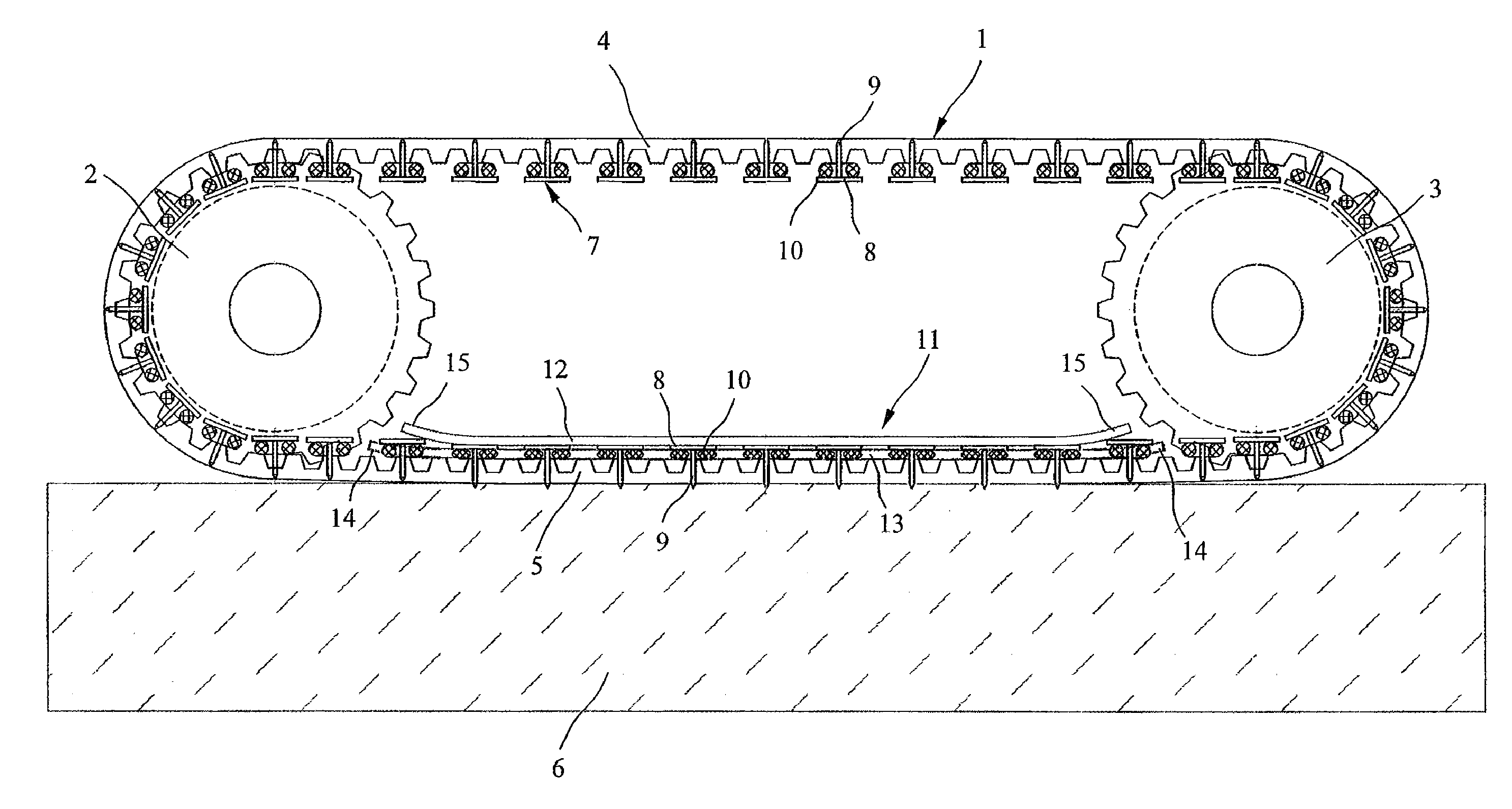
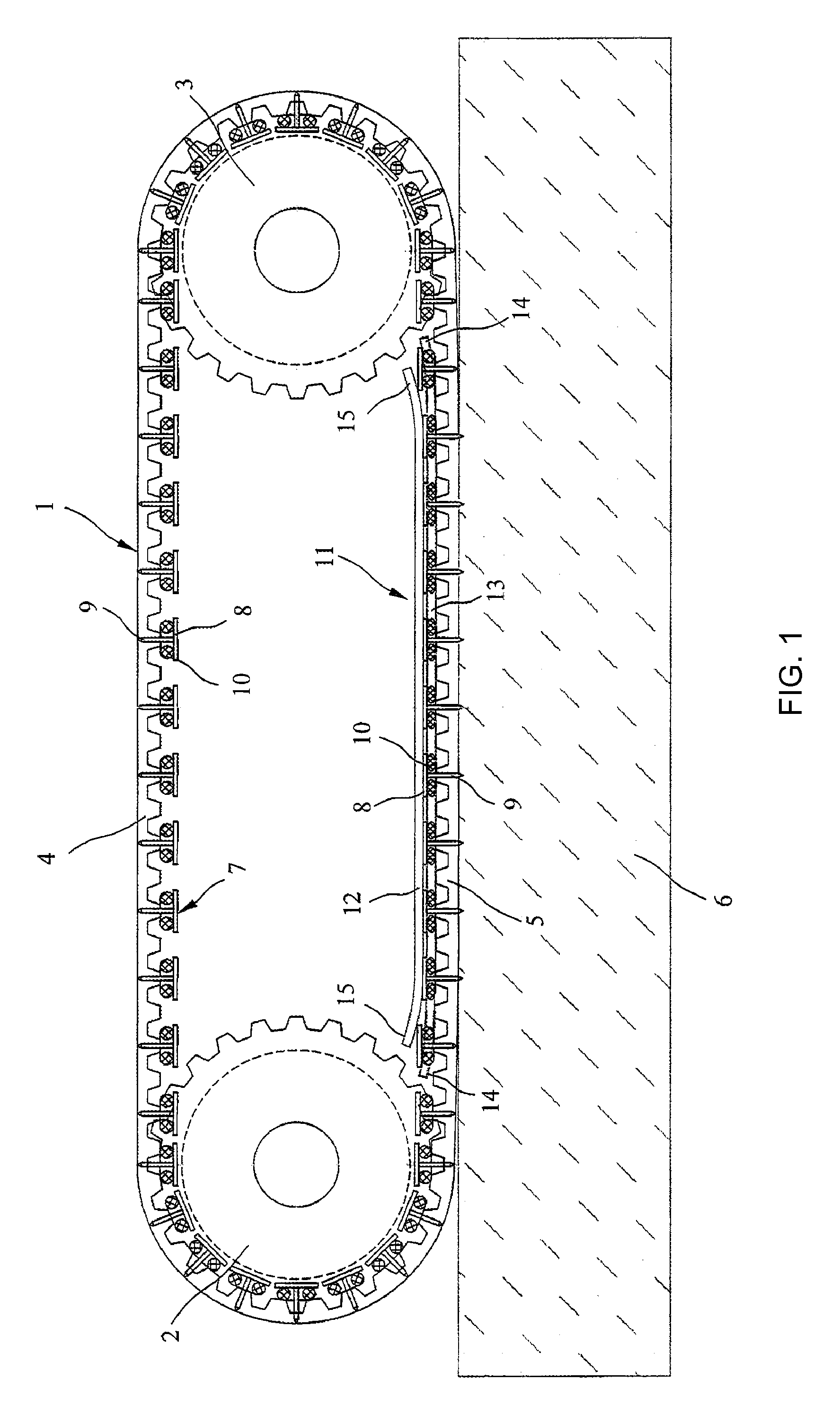
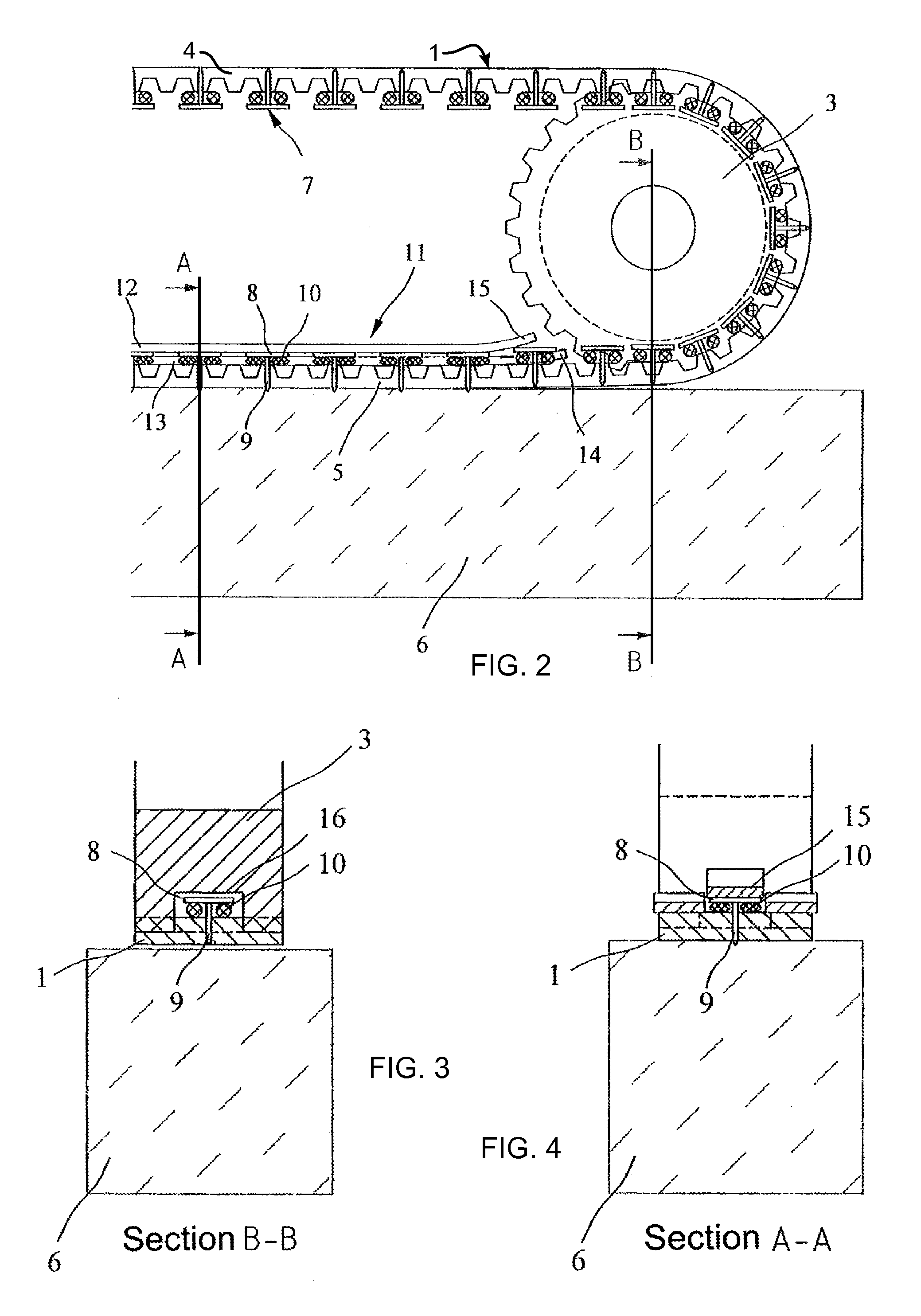
[0018]The belt drive shown schematically in FIG. 1 contains a belt-shaped drive element 1 designed here as a toothed belt that is conducted via two drive or deflection disks 2 and 3 constructed here as toothed disks. The belt drive is placed in such a manner that the upper end 4 of the belt-shaped drive element 1 is free, whereas the lower end 5 of the belt-shaped drive element 1 faces with its outside a longitudinal side of a wooden beam transported in the longitudinal direction or another moved component 6.

[0019]In the depicted exemplified embodiment, the belt drive is part of a measuring device to detect the movement of the component 6 that is moved in the longitudinal direction, wherein one of the two drive or deflection disks 2 or 3 is connected to a nondepicted sensor or another suitable device for the detection of the rotary movement of the drive or deflection disks 2 and 3. The drive element 1 is adjacent to the component 6 that is moved in the longitudinal direction, so tha...


PUM


Abstract

The invention concerns a belt or chain drive with at least one belt-shaped or chain-shaped drive element (1) conducted via drive or deflection disks (2, 3). For the accurate detection of the movement or for the exact transport of a component, movable entraining elements (7) are located in the belt-shaped or chain-shaped drive element (1) transverse to the movement direction of the drive element (1), between a withdrawal position and an extended entraining position, and an actuation device (11), by means of which the entraining elements (7) can be moved into the entraining position in a non-curved area of the drive element (1), is assigned to the drive element (1).

Description

CROSS REFERENCE TO RELATED APPLICATION[0001]This application claims priority under 35 U.S.C. §119 to German Patent Application No. 10 2011 104 177.3 filed 14 Jun. 2011, the entire contents of which are incorporated herein by reference.FIELD OF THE INVENTION[0002]The invention concerns a belt or chain drive with at least one belt-shaped or chain-shaped drive element, which is conducted via drive or deflection disks.BACKGROUND OF THE INVENTION[0003]Belt or chain drives of the type mentioned in the beginning are usually used to transfer power between shafts at a greater distance from one another. Such belt or chain drives, however, can also be used as transport or measurement devices on assembly systems or other processing machines for the processing of wooden beams; boards, plates, or other extrusion materials. Thus, for example, wooden beams can also be transported via belt or chain drives or the movement of a wooden beam transported during processing can be detected. To detect the m...

Claims


Application Information

Patent Timeline
Patent Type & Authority Applications(United States)
IPC IPC(8): F16H7/06
CPCB27B25/04B27C1/12B27M1/08B65G15/58B65G15/42B65G19/225H01H71/08
Inventor HUNDEGGER, HANS
Owner HUNDEGGER HANS
Why Eureka
Try Eureka