Easy-to-Lay Floor Board

a technology of floor board and easy-to-lay, which is applied in the field of floor board, can solve the problems of inconvenient use, and achieve the effect of convenient use and simple structur

Active Publication Date: 2012-12-27
HONG KONG MEI LI SHENG FLOORING +1
View PDF10 Cites 18 Cited by
  • Summary
  • Abstract
  • Description
  • Claims
  • Application Information

AI Technical Summary

Benefits of technology

[0003]The purpose of the present invention is to provide an easy-to-lay floor board that is convenient for use and simple in structure.
[0004]The present invention is implemented in this fashion: the floor board comprises a four-sided base board and a four-sided surface board fixed and connected to the four-sided base board; the four-sided base board comprises a four-sided base board body and board-shaped hooking tongues that are arranged on the edges of the four-sided base board body and protrude outward from the edges of the four-sided base board body; each edge of the four-sided base board body is uniformly provided with several board-shaped hooking tongues; the underside of the edge of the four-sided base board body is provided with buckles beside the board-shaped hooking tongues, corresponding to the board-shaped hooking tongues; the positions of the board-shaped hooking tongues on two edges of the four-sided base board body and the positions of the board-shaped hooking tongues on two other edges of the four-sided base board body are arranged in a staggered manner, and the positions of the buckles on two edges of the four-sided base board body and the positions of the buckles on two other edges of the four-sided base board body are arranged in a staggered manner. At the time of use, the edge of one of the floor boards is connected edge-to-edge to the edge of another floor board, and in making such connection, the board-shaped hooking tongues and the buckles of the two edges are arranged in a staggered manner, and in this way, the board-shaped hooking tongues and the buckles on the edge of one of the floor boards can be engaged together with the buckles and the board-shaped hooking tongues of another floor board, and by adopting the form of connection with hooking tongues and buckles, even if the board-shaped hooking tongues and the buckles on one of the edges are disengaged, the board-shaped hooking tongues and the buckles on the other edge are still in an engaged status, so that the reliability of the connection of the two boards is ensured, and the floor boards laid on the floor can be connected firmly without the need for adhesive or iron nails.
[0005]Here, the four-sided base board comprises a four-sided base board skeleton frame and a functional board fixed within the four-sided base board skeleton frame; the four-sided base board skeleton frame comprises two end-to-end connected L-shaped skeleton units and the hooking tongues and buckles provided on the external edges of the L-shaped skeleton units; the horizontal skeleton end of the L-shaped skeleton unit is provided with insertion blocks while the inner side of the vertical skeleton end corresponding to the insertion blocks is provided with recesses for insertion, or the inner side of the vertical skeleton end is provided with insertion blocks while the horizontal skeleton end of the L-shaped skeleton unit corresponding to the insertion blocks is provided with recesses for insertion, wherein the insertion blocks and recesses for insertion of one of the L-shaped skeleton units are connected in a matching fashion with the recesses for insertion and insertion blocks of the other L-shaped skeleton unit by way of insertion. Because the base board is composed of the four-sided base board skeleton frame, which is itself composed of two L-shaped skeleton units and the functional board fixed inside the four-sided base board skeleton frame, the members that constitute the base board are small in area, easily fabricated, and do not need equipments that require large investment; and after the area is reduced, the members cannot be easily distorted, so that the stability of quality is effectively ensured. With regard to the adoption of functional boards, corresponding functional boards may be adopted according to needs in actual use, thereby enriching the varieties and functions of the products.

Problems solved by technology

Existing floor boards are generally composed of a board body and protruding connectors arranged around the board body; when the floor boards are laid, one of the floor boards is laid over the protruding connectors of another floor board, and the two boards are fixed and connected with adhesive or iron nails; because this type of floor board must be fixed and connected with adhesive or iron nails, it is very inconvenient for use.

Method used


Image

  • Easy-to-Lay Floor Board
  • Easy-to-Lay Floor Board
  • Easy-to-Lay Floor Board

Examples


embodiment 1

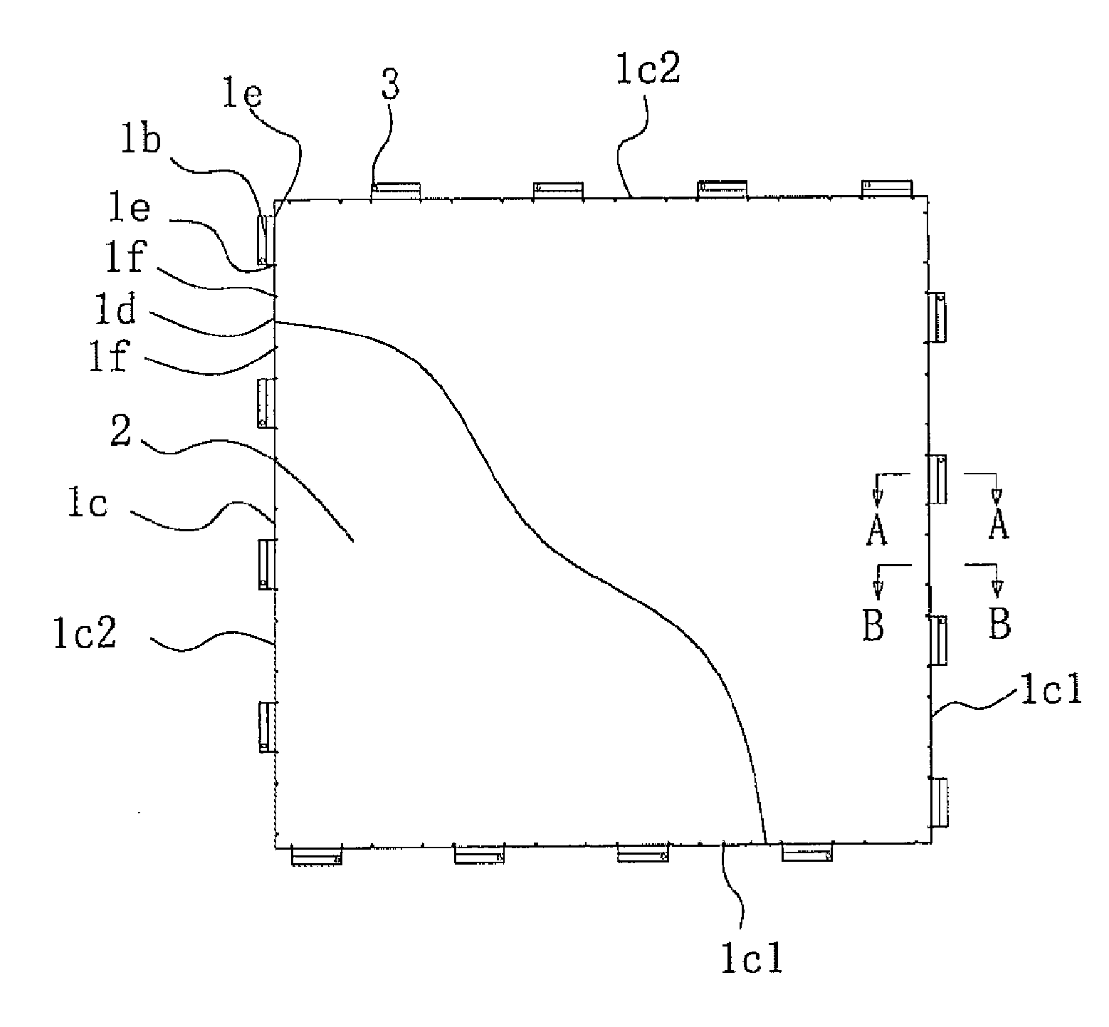
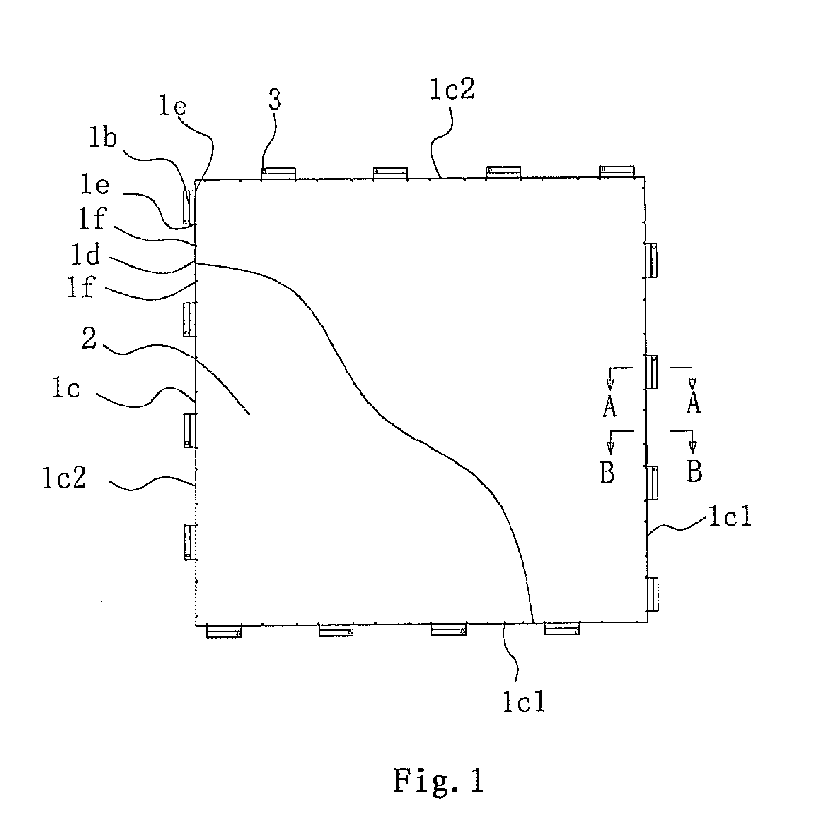
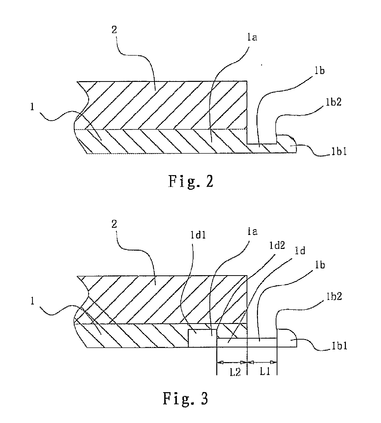
[0033]As shown in FIGS. 1, 2, 3, 4, 5, 6 and 7, the floor board of the present invention comprises the square base board 1, the square surface board 2 fixed and connected to the square base board 1, and the decorative strip 4; the square base board 1 comprises the square base board body 1a and the board-shaped hooking tongue 1b that is provided on the edge of the square base board body 1a; each edge of the square base board body 1a is uniformly provided with several board-shaped hooking tongues 1b; the underside of the edge 1c of the square base board body 1a is provided with a buckle 1d beside the board-shaped hooking tongue 1b, corresponding to the board-shaped hooking tongue 1b; the positions of the board-shaped hooking tongues 1b on two edges 1c1 of the square base board body 1a and the positions of the board-shaped hooking tongues 1b on two other edges 1c2 of the square base board body 1a are arranged in a staggered manner, and the positions of the buckles 1d on two edges 1c1 o...

embodiment 2

Decorative Strip Embodiment 2

[0037]As shown in FIGS. 8 and 9, the same side of the decorative strip 4 is provided with board-shaped hooking tongues 4b that protrude outward from the side edge of the decorative strip body 4a and correspond to the buckles id as provided on the underside of the edge of the square base board body 1a, as well as the buckles 4c that correspond to the hooking tongues 1b as provided on the edge of the square base board body 1a. The thickness of the decorative strip body 4a is consistent with the thickness of the square base board 1 and the square surface board 2 put together. The decorative strip in Embodiment 2 may be applied to the decoration of the margins of the laid floor boards by way of connection with the hooking tongues 1b and the buckles 1d on the margins of the laid floor boards.

embodiment 3

Decorative Strip Embodiment 3

[0038]As shown in FIGS. 10 and 11, on the basis of Decorative Strip Embodiment 2, with regard to this embodiment, the upper surface of the decorative strip body 4a is a cambered surface, and an insertion slot 4e is formed between one side 4g of the cambered surface and the board-shaped hooking tongue 4b. In this way, at the time of use, one side 4g of the cambered surface tightly adjoins the square surface board 2, while the other side 4f of the cambered surface forms a natural transition with the floor, creating a point of access.


PUM


Abstract

Aspects relate to improved floor boards. Certain embodiments may be laid and fixed without the need for fixing with adhesive or nails. Example floor boards are convenient for use and simple in structure, and after a decorative strip is adopted, it further has the advantage of good decorative effects. In one embodiment, a floor board includes a four-sided surface board connected to a four-sided base board. In one embodiment, positions of board-shaped hooking tongues on two edges of the base board body and positions of board-shaping hooking tongues on two other edges of the base board body are arranged in a staggered manner, and the positions of buckles on two edges of the base board body and the positions of buckles on two other edges of the base board body are arranged in a staggered manner.

Description

TECHNICAL FIELD[0001]The present invention relates to a floor board.BACKGROUND ART[0002]Existing floor boards are generally composed of a board body and protruding connectors arranged around the board body; when the floor boards are laid, one of the floor boards is laid over the protruding connectors of another floor board, and the two boards are fixed and connected with adhesive or iron nails; because this type of floor board must be fixed and connected with adhesive or iron nails, it is very inconvenient for use.SUMMARY OF THE INVENTION[0003]The purpose of the present invention is to provide an easy-to-lay floor board that is convenient for use and simple in structure.[0004]The present invention is implemented in this fashion: the floor board comprises a four-sided base board and a four-sided surface board fixed and connected to the four-sided base board; the four-sided base board comprises a four-sided base board body and board-shaped hooking tongues that are arranged on the edge...

Claims


Application Information

Patent Timeline
Patent Type & Authority Applications(United States)
IPC IPC(8): E04B5/00E04F13/21
CPCE04F2201/0153E04F15/02194E04B5/02E04F2201/043E04F2201/0138E04F2201/022E04F15/02038E04C2/38E04C2/50E04F15/02E04F2201/09
Inventor HUANG, HUANWEN
Owner HONG KONG MEI LI SHENG FLOORING
Why Eureka
Try Eureka