
Garment, in particular a compression garment for medical use

a compression garment and medical technology, applied in the field of compression garments for medical use, can solve the problems of difficult reworking operation, difficult to solve, and relatively ineffective as medical compression stockings, and achieve the effect of avoiding any risk of strangulation

Inactive Publication Date: 2012-12-27
RADIANTE OY
View PDF15 Cites 34 Cited by
  • Summary
  • Abstract
  • Description
  • Claims
  • Application Information

AI Technical Summary

Benefits of technology

[0015]The technical problem is solved in accordance with the invention by means of a garment including a knitted, circumferentially-extending welt portion having an anti-slip zone comprising a high friction yarn integrally formed on an inner face of a main garment portion such that the high friction yarn contacts a wearer's skin to increase the anti-slip properties of the garment.
[0032](c) integrally-forming a knitted welt portion including the high-friction yarn circumferentially onto an inner, skin-contacting face of the knitted welt portion to define an anti-slip zone such that the high friction yarn contacts a wearer's skin to increase the anti-slip properties of the garment.

Problems solved by technology

Although the question of preventing stockings or socks from slipping down has already given rise to numerous solutions, it should nevertheless be understood that in the special circumstance of compression garments for medical use the problem is more difficult to solve since it is necessary simultaneously to take care to avoid any excessive compression in the welt portion of the garment since that would give rise to a tourniquet effect with a risk of strangulation that is completely undesirable in the medical field, in particular concerning the risk of thrombosis.
Proposals have sometimes been made to use bands that concern only a fraction of the circumference of the anti-slip welt portion, as shown in document U.S. Pat. No. 3,975,929 A. Proposals have also been made to coat a localized region of the inside face of the welt portion of a stocking with an anti-friction material so as to obtain small zones of coating that come directly into contact with the wearer's skin, as shown in document U.S. Pat. No. 3,983,870 A. Although that solution might look attractive, it suffers from the drawback of requiring a difficult re-working operation for achieving localized coating in the welt zone of the compression stocking.
Nevertheless, in that document, the ribbon extends therapeutic action of the stocking, and as a result runs a risk of strangulation, which makes it relatively ineffective as a medical compression stocking.
All of the above-mentioned techniques provide for adding a more or less elaborate elastic garter band, but the mere fact of adding automatically implies a separate joining operation that complicates fabrication of the compression garment.
It would be very tempting to avoid that constraint by providing a coating of silicone directly on the inside face of the welt portion of the stocking so as to form a circumferential anti-slip band, however that technique would involve an additional fabrication step (like stitching on an additional garter band), and would also make it more complicated to control the pressure exerted at that level.
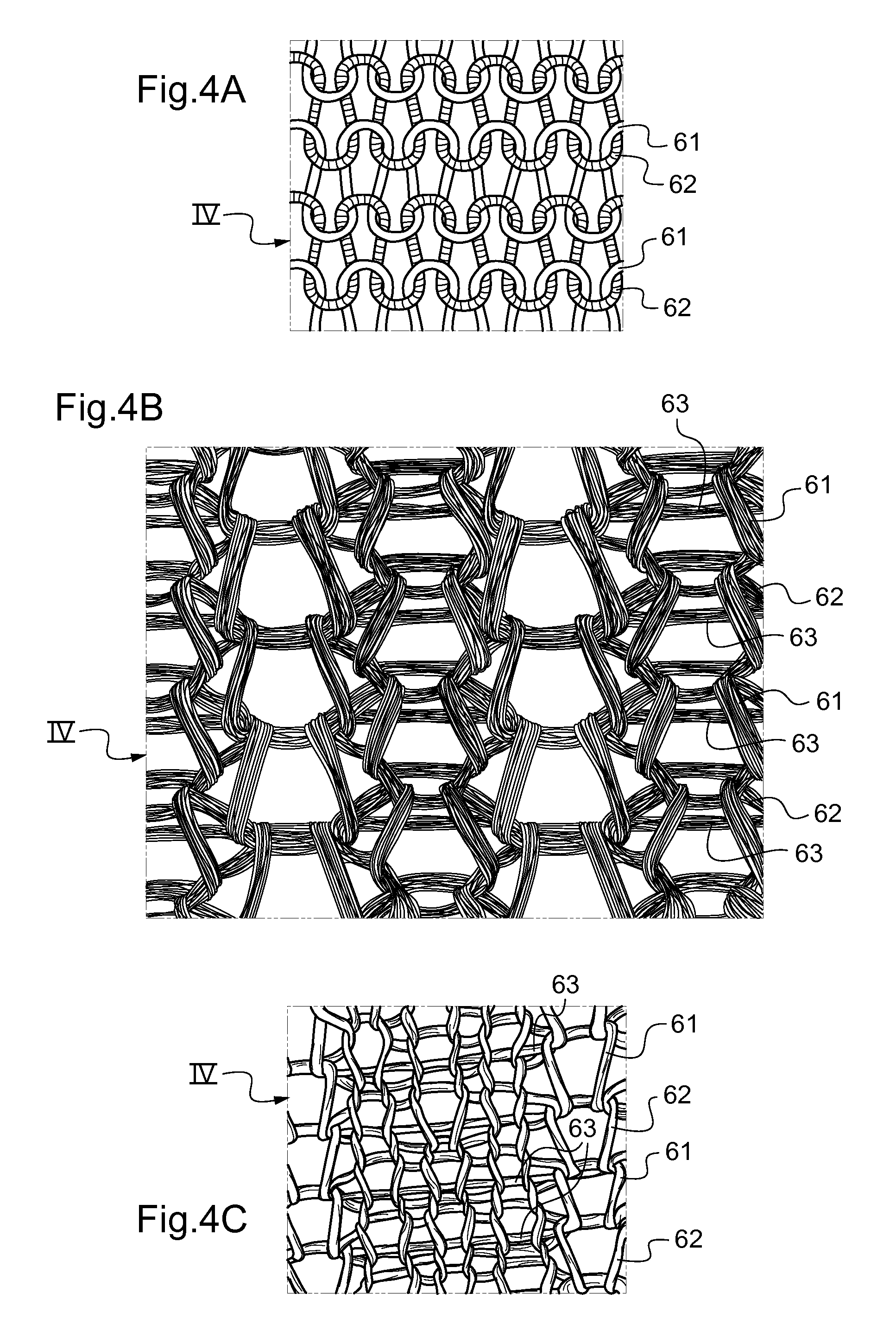
The drawback of having a laid-in yarn that is the only high-friction element is that the yarn must necessarily be of considerable weight in order to achieve a contact area that is capable of providing the looked-for anti-slip effect (as can be seen in the photographs of FIGS. 5 and 6) such that, in practice, its weight must always be greater than 300 decitex (dtex), whereas a knitting yarn conventionally has a weight lying in the range 60 dtex to 100 dtex.
Nevertheless, such an approach is not satisfactory since any increase in the weight of the high-friction laid-in yarn for increasing contact area with the skin of the wearer of the garment will necessarily have the effect of making the yarn springier and of increasing the pressure exerted on the leg by the zone in question.
Under such circumstances, in order to avoid the above-mentioned drawback, and in order to reduce the clamping pressure that is exerted, the only solution consists in spacing apart the rows of laid-in yarn, but that is then detrimental to contact area for a given height of the anti-slip end welt portion.
Nevertheless, that approach is not satisfactory either, since by increasing the number of rows without overlap for the high-friction laid-in yarn, the yarn becomes freer and freer and thus catches more easily and forms undesirable loops.

Method used


Image

  • Garment, in particular a compression garment for medical use
  • Garment, in particular a compression garment for medical use
  • Garment, in particular a compression garment for medical use

Examples


Embodiment Construction

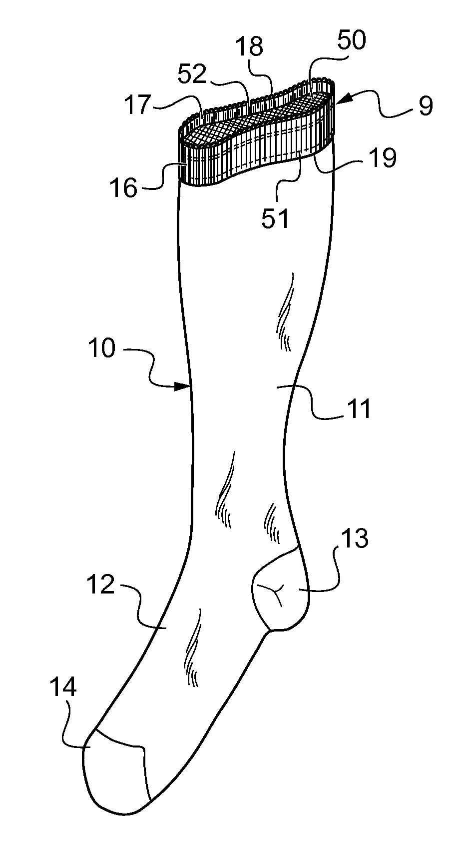
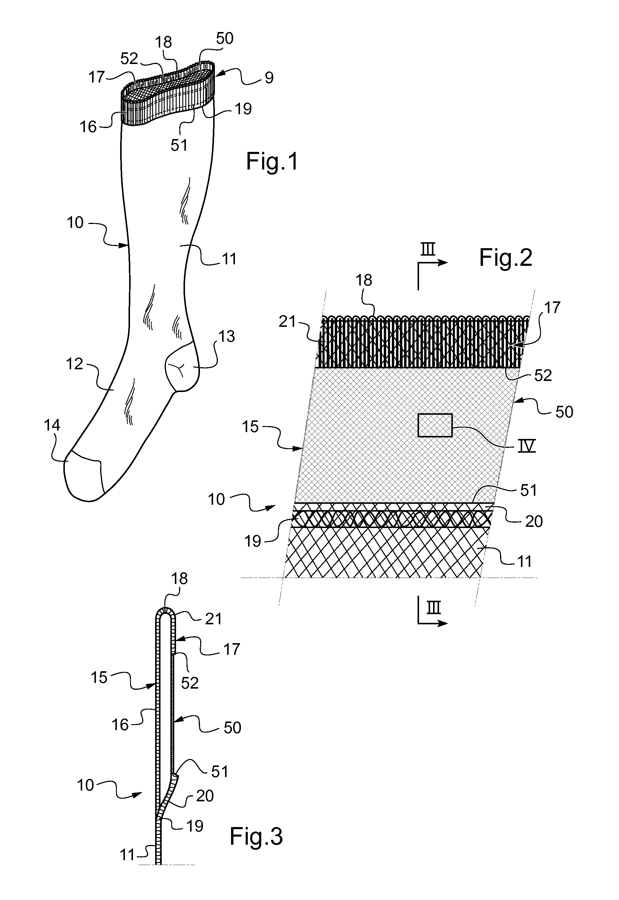
[0049]FIG. 1 shows a garment in accordance with the invention, here implemented in the form of a compression stocking or sock, referenced 10.

[0050]The compression garment 10 has a main portion 11 of elastic knit that serves to compress the portion of the leg on which the garment is positioned in order to treat lymphatic or venous insufficiency. The foot portion 12 has a heel 13 and a toe 14. The main portion 11 is also extended upwards by a welt portion also called here top portion referenced 9. The inner face of the top portion 9 in contact with the wearer's skin is conformed to provide an anti-slip effect promoting holding of the compression garment 10 in position. Of course, the inner face of the welt portion is also the inner face of the main portion.

[0051]As shown in FIGS. 1 to 3, and in accordance with an essential characteristic of the invention, the top portion 9 of the compression garment 10 is folded so as to define a folded edge 15 with an outside welt 16 and an inside we...


PUM

PropertyMeasurementUnit
heightaaaaaaaaaa
frictionaaaaaaaaaa
circumferenceaaaaaaaaaa

Abstract

The invention relates to a garment (10; 100) including a knitted, circumferentially-extending welt portion having a anti-slip zone (50) comprising a high friction yarn (61, 62, 63) integrally formed on a inner face of a main garment portion (11; 110) such that the high friction yarn contacts a wearer's skin to increase the anti-slip properties of the garment. The invention also relates to a method for constructing such a garment.

Description

[0001]The present invention relates to garments of the type comprising a main portion to be positioned on a part of the body of a wearer. The garments may notably, but not exclusively, be compression garments for medical use suitable for a leg or an arm. The main portion thereof thus serves to compress the limb on which the garment is positioned, in order to treat lymphatic or venous insufficiency by exerting pressure that is degressive from the bottom towards the top of the garment.[0002]More particularly, the invention relates to garments that are fitted at a welt portion thereof with means for providing an anti-slip effect so as to enhance holding of the garment in place.BACKGROUND OF THE INVENTION[0003]Although the question of preventing stockings or socks from slipping down has already given rise to numerous solutions, it should nevertheless be understood that in the special circumstance of compression garments for medical use the problem is more difficult to solve since it is ...

Claims


Application Information

Patent Timeline
Patent Type & Authority Applications(United States)
IPC IPC(8): D04B1/26D04B1/24
CPCA61F13/08D04B1/265D04B1/106D04B1/18
Inventor CLEMENDOT, OLIVIER
Owner RADIANTE OY
Learn More