Automatic balancing valve

a technology of automatic balancing and balancing valve, which is applied in the direction of space heating and ventilation details, heating types, and domestic heating details, etc., can solve the problems of increasing energy consumption, difficult operation, and a rather long time to perform

Active Publication Date: 2012-12-27
F PETTINAROLI
View PDF10 Cites 26 Cited by
  • Summary
  • Abstract
  • Description
  • Claims
  • Application Information

AI Technical Summary

Benefits of technology

[0018]The reference element is preferably a portion of a locking element of the ring nut. In particular, the locking element can move between a first position in which the rotation of the ring nut is enabled and a second position in which the rotation of the ring nut is prevented.

Problems solved by technology

For example, referring specifically to heating and / or cooling systems in places such as schools, hospitals, hotels, shopping centers and the like, the variation in the different flow rates as referred to the design data would inevitably lead to temperature differences in the different places which, apart from giving rise to physical discomfort, entail an increase in energy consumption.
This operation can often be difficult and takes a rather long time to perform, especially when the valves are installed in inaccessible places, or if the external control itself is hard to reach due to the size of the valve body or the actuating member of the shutter if the valve is installed with unfavorable orientation in positions difficult to reach, for instance when accessing through ceilings or false ceilings.
In other known valves the adjustment of the maximum flow rate can be performed by operating a control located on the opposite side of the shutter actuating member: this allows to avoid removing the actuating member, although the adjustment can be difficult if the control is facing the inside of the space occupied by the valve, as it normally occurs to make instead access to the shutter actuating member easier.

Method used


Image

  • Automatic balancing valve
  • Automatic balancing valve
  • Automatic balancing valve

Examples


Embodiment Construction

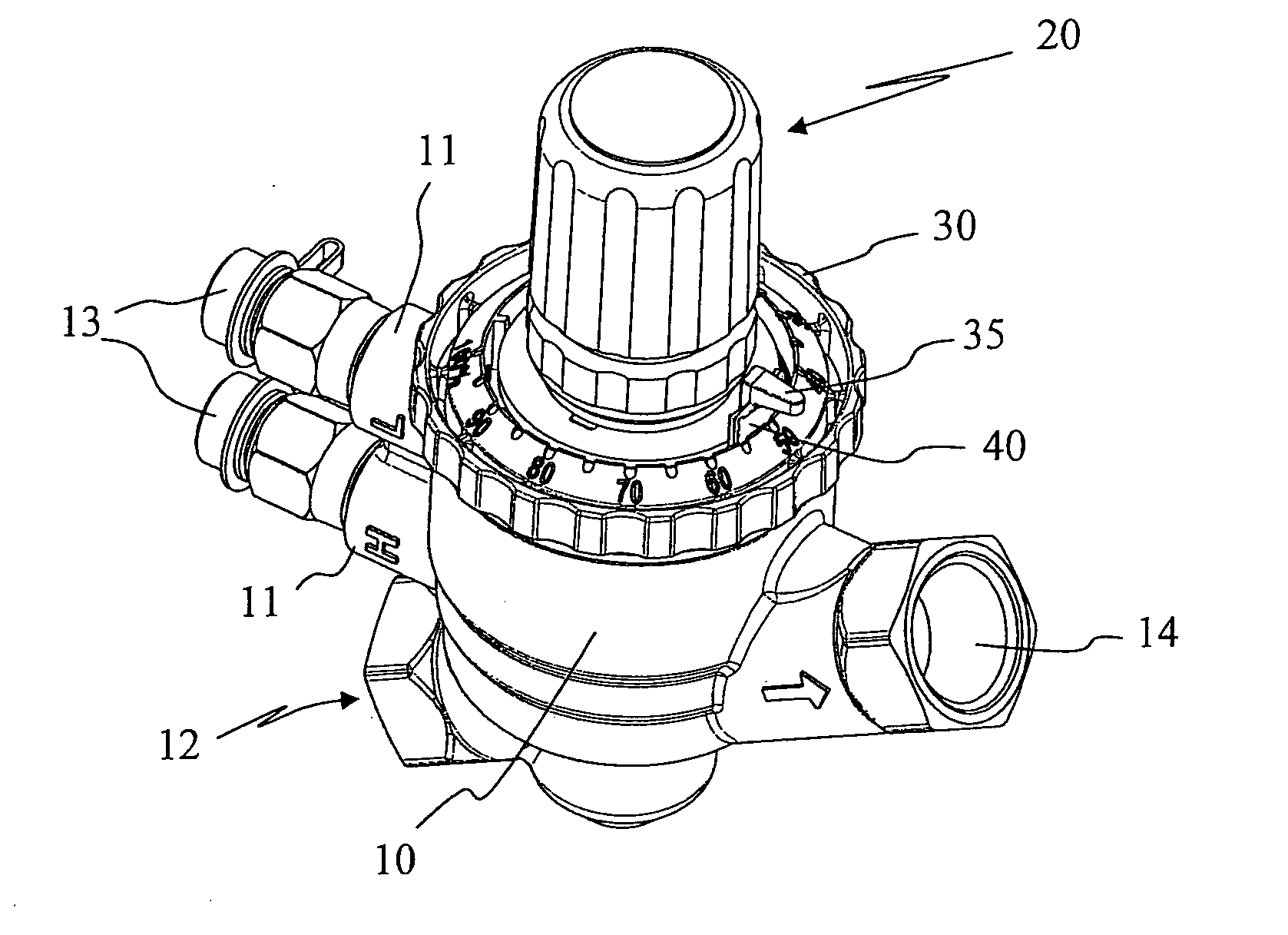
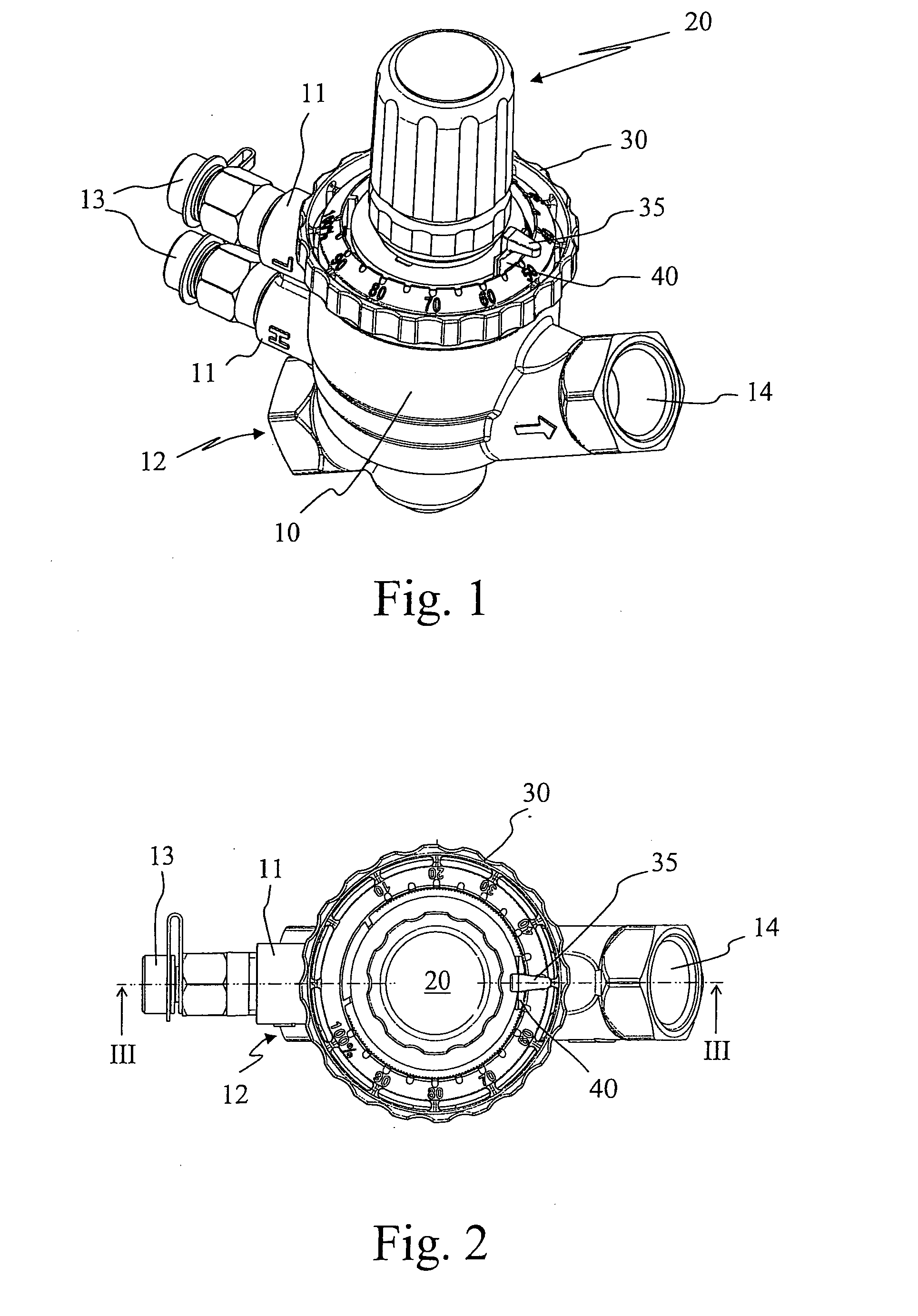
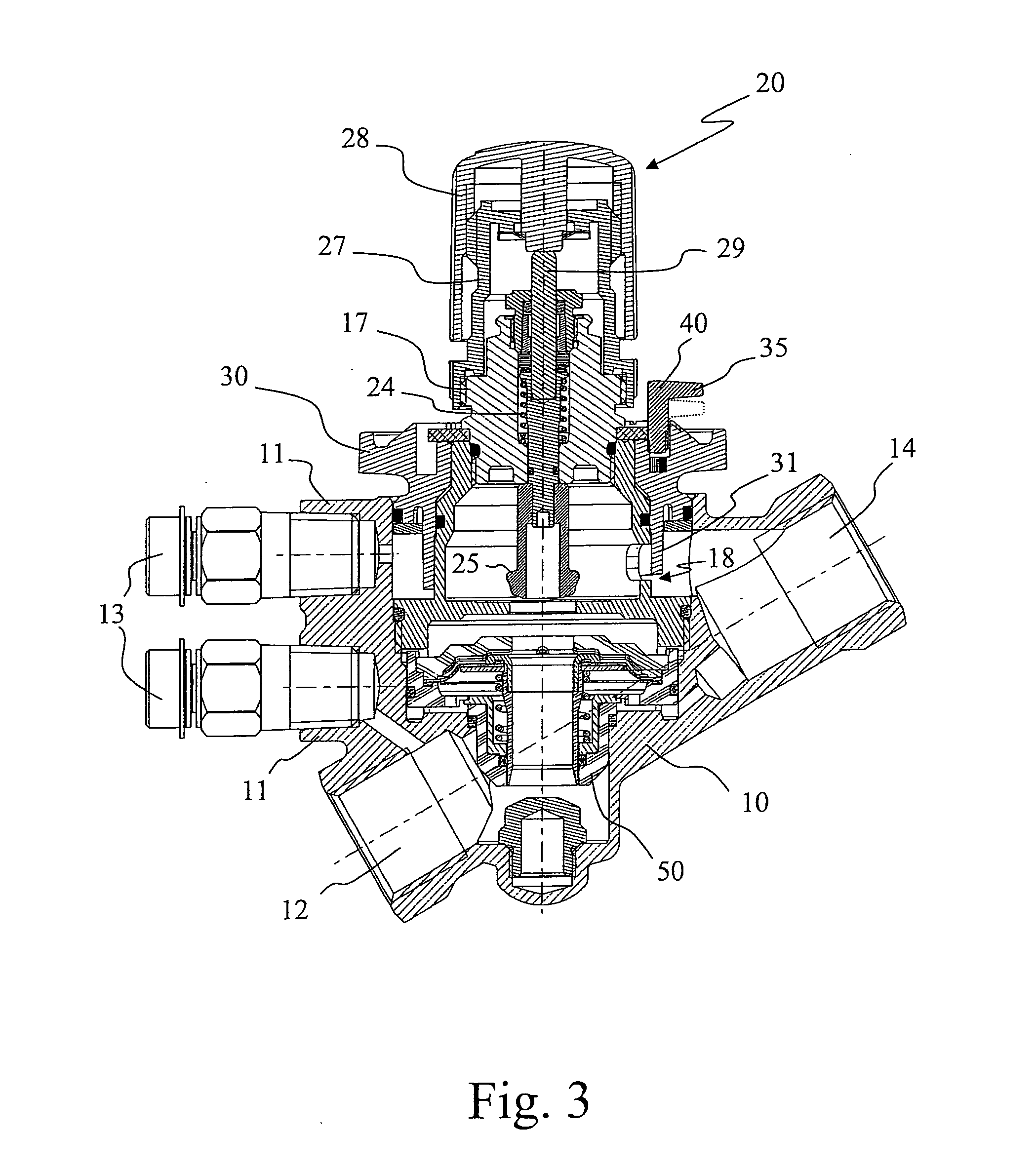
[0025]Referring initially to the embodiment illustrated in FIGS. 1 to 3, a balancing valve according to the invention comprises a valve body 10 having an inlet opening 12 and an outlet opening 14.

[0026]On the inlet opening side 12 are also two connectors 11, closed with their respective plugs 13, which allow to temporarily connect probes that can detect the pressure and / or flow values of the valve installed. These values are generally transferred to a measuring instrument to determine the operating features of the system section in which the valve is installed and the proper operation of the valve thereof.

[0027]In the embodiment shown here, there is a manual actuating member 20 for the shutter and a ring nut 30 placed below the actuating member 20 and aligned axially therewith.

[0028]As is evident from the view in FIG. 2, the dimensions of the ring nut 30 are larger in the plan view compared to the plan view dimensions of the actuating member 20. The ring nut 30, which is the control...


PUM


Abstract

An automatic balancing valve is disclosed which is equipped with choking means that can be operated manually with a ring nut placed below the actuating member of the shutter and aligned axially therewith. Advantageously, the dimensions of the ring nut are larger in plan view compared to the plan view dimensions of the actuating member so as to allow its rotation without removing the actuating member.

Description

TECHNICAL FIELD OF THE INVENTION[0001]The present invention relates to an automatic balancing valve, such as a valve that can be installed in heating and / or cooling systems made up of several distinct sections, to properly adjust the supply of thermo-convective fluid flow to each section of the system.PRIOR ART[0002]In general, in hydraulic systems consisting of multiple sections, the fluid flow rates in each section are established during design stage but may also vary during operation.[0003]For example, referring specifically to heating and / or cooling systems in places such as schools, hospitals, hotels, shopping centers and the like, the variation in the different flow rates as referred to the design data would inevitably lead to temperature differences in the different places which, apart from giving rise to physical discomfort, entail an increase in energy consumption.[0004]Balancing valves typically include a valve body having an inlet opening and an outlet opening. The fluid ...

Claims


Application Information

Patent Timeline
Patent Type & Authority Applications(United States)
IPC IPC(8): G05D7/01
CPCF24D19/1015G05D7/0113F24D19/1036G05D7/0106Y10T137/776Y10T137/7793Y10T137/87917Y10T137/7782
Inventor PETTINAROLI, GIULIOSPAGNOLO, LIBORIO
Owner F PETTINAROLI
Why Eureka
Try Eureka