Wheelbarrow leg stabilizer

a technology of leg stabilizer and wheelbarrow, which is applied in the direction of hand carts, hand carts with one axis, transportation and packaging, etc. it can solve the problems of increasing static friction or “starting friction” and increasing the friction between the ground and the wheelbarrow. , to achieve the effect of increasing the starting friction

Active Publication Date: 2012-12-27
IAMS
View PDF10 Cites 6 Cited by
  • Summary
  • Abstract
  • Description
  • Claims
  • Application Information

AI Technical Summary

Benefits of technology

[0006]The disclosed and claimed concept provides for a leg stabilizer having a slip resistant lower surface. Preferably, the slip resistant lower surface includes a plurality of edges structured to engage the ground and thereby increase the starting friction. More preferably, the edges are part of a deformation in the le...

Problems solved by technology

Thus, there is an increase in the static friction or “starting friction” between the ground and the wheelbarrow.
While this is not a substantial problem when a wheelbarrow is on flat ground, sliding becomes an issue on a sloped surface.
That is, ...

Method used


Image

  • Wheelbarrow leg stabilizer
  • Wheelbarrow leg stabilizer
  • Wheelbarrow leg stabilizer

Examples


Embodiment Construction

[0014]As used herein, “coupled” means a link between two or more elements, whether direct or indirect, so long as a link occurs.

[0015]As used herein, “directly coupled” means that two elements are directly in contact with each other.

[0016]As used herein, “fixedly coupled” or “fixed” means that two components are coupled so as to move as one while maintaining a constant orientation relative to each other. The fixed components may, or may not, be directly coupled.

[0017]As used herein, the word “unitary” means a component is created as a single piece or unit. That is, a component that includes pieces that are created separately and then coupled together as a unit is not a “unitary” component or body.

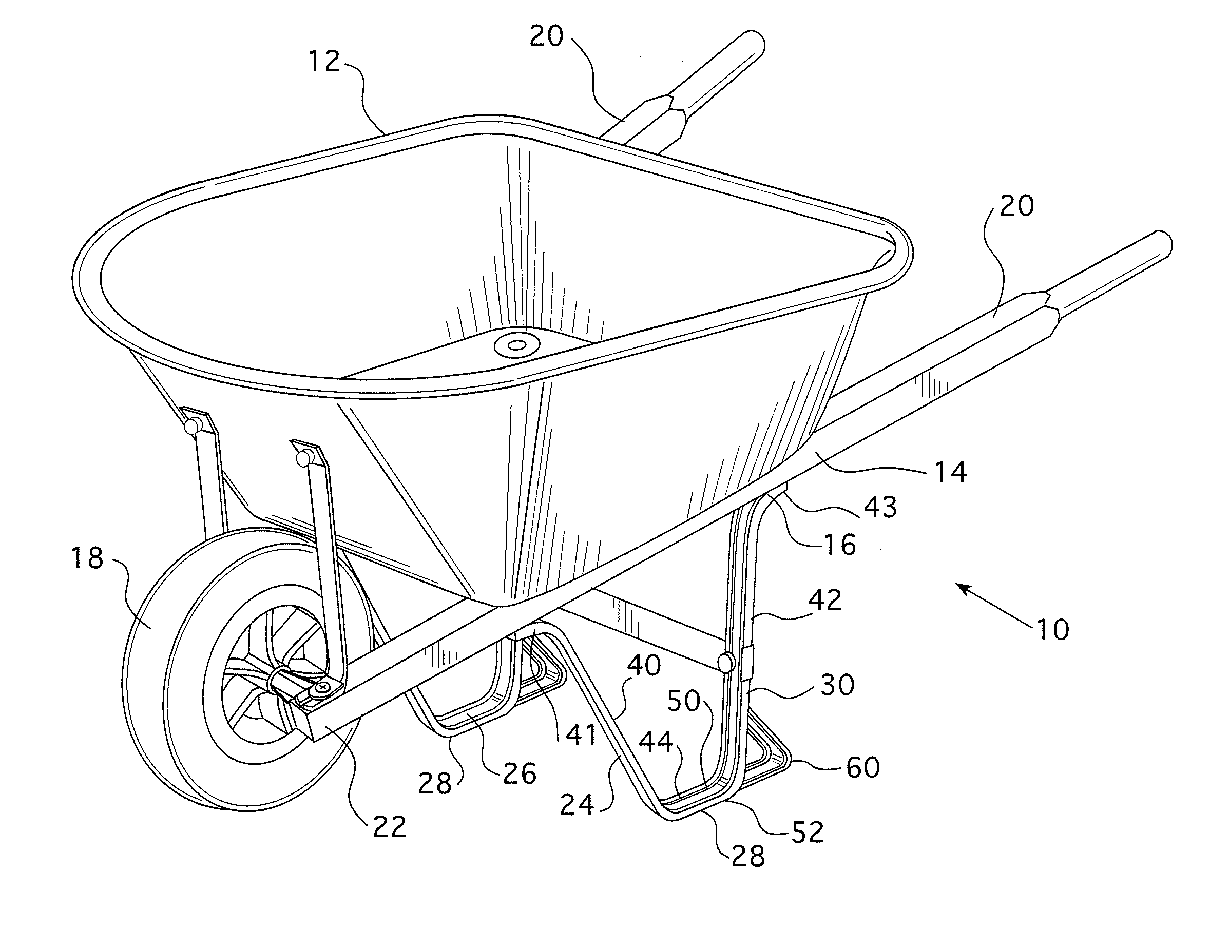
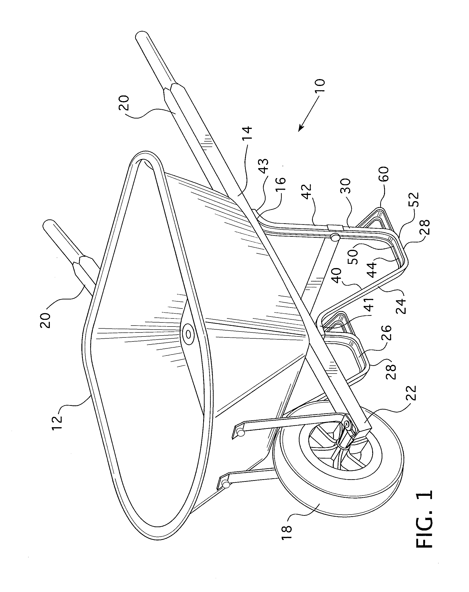
[0018]As used herein, directional terms, such as, but not limited to, “forward,”“back,”“right,”“left,”“upper,”“lower,” and “lateral” correspond to the orientation of the wheelbarrow from the perspective of a user standing at the handle portion looking toward the hopper—that is, the normal p...


PUM


Abstract

A wheelbarrow leg stabilizer having a slip resistant lower surface is provided. Preferably, the slip resistant lower surface includes a plurality of edges structured to engage the ground and thereby increase the starting friction. More preferably, the edges are part of a deformation in the leg stabilizer body. When the stabilizer body is constructed from a generally planar metal member, the deformations may be punched in the stabilizer body thereby creating openings adjacent the deformations. This configuration provides for both an edge that engages the ground but also a face that creates a larger contact surface with the ground.

Description

BACKGROUND OF THE INVENTION[0001]1. Field of the Invention[0002]The present invention relates to wheelbarrows and, more specifically, to a wheelbarrow having a leg stabilizer with a slip resistant surface.[0003]2. Description of the Related Art[0004]As is well known, a wheelbarrow has a hopper or tray and a frame assembly. The frame assembly includes a plurality of rigid frame members, at least one wheel, typically disposed at the front of the tray, and a pair of handles extending behind the tray. Two elongated frame members typically form a yoke to support the wheel and the backwardly extending handles. The frame members further include at least one, and typically two, legs structured to engage the ground when the wheelbarrow is at rest. The legs may be columnar members, i.e. generally straight posts, or, more typically, are generally U-shaped members having two “tines” and a “bight.” The bight is the portion of the leg members that engages the ground. The tines extend upwardly and...

Claims


Application Information

Patent Timeline
IPC IPC(8): B62B7/02
CPCB62B1/18B62B5/00B62B1/008B62B5/049B62B1/20B62B5/0003B62B2301/25
Inventor ALBERT, BARRY R.MARSHALL, DANIEL F.MULLEN, JOSHUA O.LUPEY, JR., MICHAEL J.
Owner IAMS
Why Eureka
Try Eureka