Charger for electronic device, electronic device, and charging method

a technology of electronic devices and chargers, applied in electric vehicles, electric power, transportation and packaging, etc., can solve the problems of inability to acquire information (specified voltage, specified current, etc.) necessary for charging from the connected electronic device, and the inability of electronic devices to perform usb communication,

Active Publication Date: 2012-12-27
NIKON CORP
View PDF3 Cites 18 Cited by
  • Summary
  • Abstract
  • Description
  • Claims
  • Application Information

AI Technical Summary

Benefits of technology

[0009]Accordingly, it is an object of the present invention to provide a charger for an electronic device, an electronic device, and a charging method that stably charge a rechargeable battery even when charging information cannot be acquired from another electronic device, which serves as a connection origin.

Problems solved by technology

For 100 mA, a problem occurs in that when there is not enough power, a CPU of a charger in an electronic camera cannot be activated.
Thus, information (specified voltage, specified current, etc.) necessary for the charging cannot be acquired from the connected electronic device.
Thus, the electronic device cannot perform USB communication and therefore cannot determine the specified current of the AC adapter.
In this manner, a rechargeable battery cannot be stably charged when charging information, such as the specified current of another electronic device serving as the connection origin cannot be acquired.
This problem does not occur only in electronic cameras and also occurs in many types of electronic devices that charge its rechargeable battery with bus power.

Method used


Image

  • Charger for electronic device, electronic device, and charging method
  • Charger for electronic device, electronic device, and charging method
  • Charger for electronic device, electronic device, and charging method

Examples


first embodiment

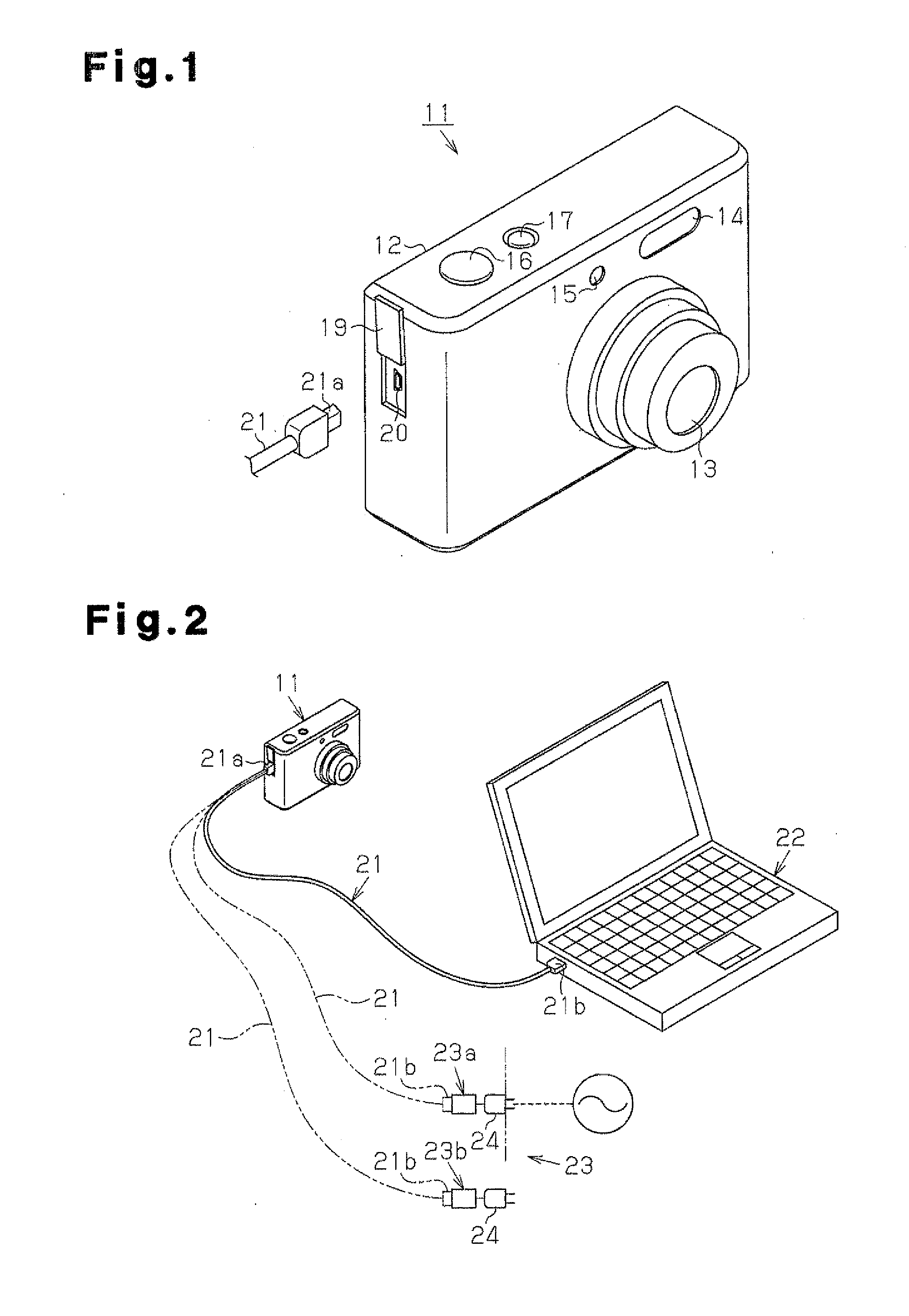
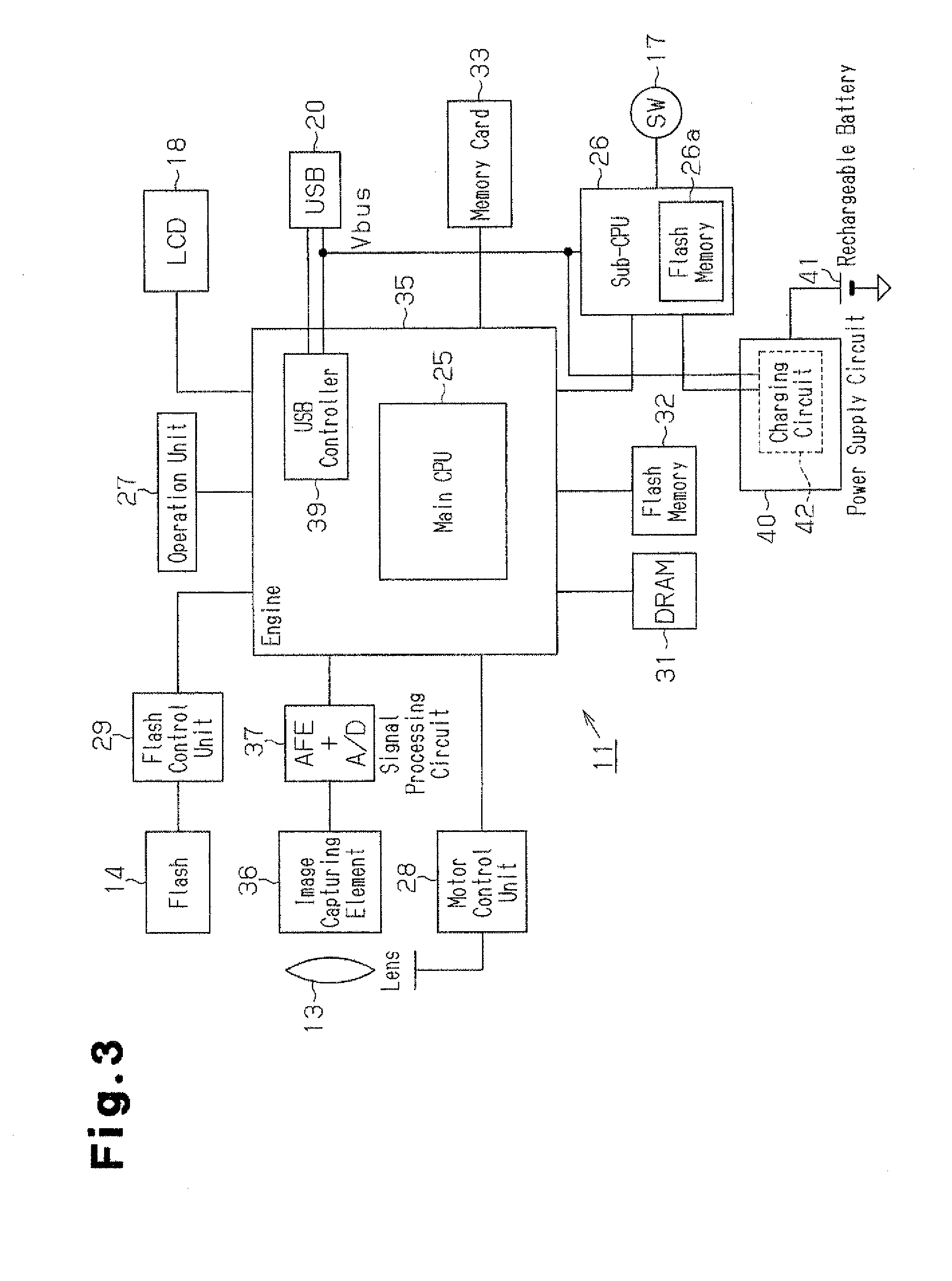
[0023]An electronic device according to a first embodiment of the present invention will now be discussed with reference to FIGS. 1 to 5. Here, the electronic device is an electronic still camera 11.

[0024]As shown in FIG. 1, the electronic still camera 11 (digital still camera) of the present embodiment includes a camera body 12 having the shape of a rectangular cuboid. An image capturing lens unit 13 is arranged in the front central part of the camera body 12. A flash 14 (strobe light emitting unit) and an emission window 15 are arranged on the camera body 12 at two locations above the image capturing lens unit 13. The emission window 15 emits infrared light, ultrasonic waves, or the like towards a subject to perform focusing.

[0025]A release button 16, which a photographer pushes (i.e., activates) when initiating an image capturing operation with the electronic still camera 11, is arranged at the left end on the upper surface of the camera body 12 as viewed in FIG. 1. A power switc...

second embodiment

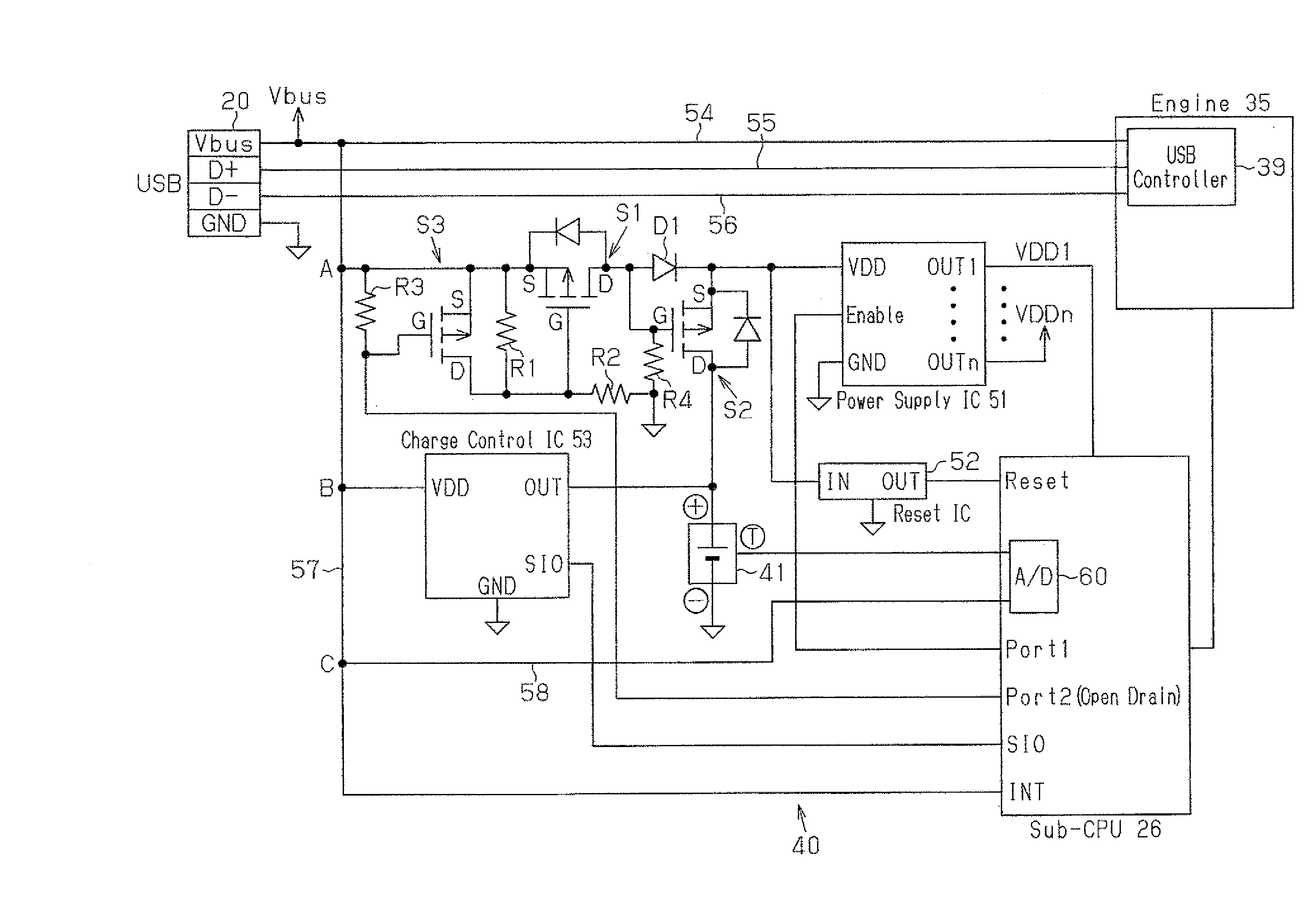
[0086]A second embodiment will now be discussed with reference to FIG. 6. The second embodiment differs from the first embodiment in that the main CPU 25 is activated to acquire the standard-specified current information (specified power supply information) of another electronic device serving as the connection origin with the USB communication. Otherwise, the structure of the electronic still camera 11 is the same as the first embodiment. Thus, only the contents of the charging control process will be described below in detail. In the present embodiment, at least the main CPU 25, the sub-CPU 26, and the power supply circuit 40 form the charger for charging the rechargeable battery 41.

[0087]Referring to FIG. 6, when the sub-CPU 26 detects connection of the USB cable 21 (affirmative determination in step S210) and determines that the temperature of the rechargeable battery 41 is in a chargeable range (affirmative determination in step S220), the sub-CPU 26 proceeds to step S230 and a...

third embodiment

[0093]A third embodiment will now be discussed with reference to FIG. 7. In the third embodiment, the measurement value differs from each of the above-described embodiments. More specifically, in each of the embodiments described above, the sub-CPU 26 controls the charging current amount Ib by directly using the measurement value (measurement voltage Vm). In the third embodiment, the sub-CPU 26 determines the voltage drop amount and the voltage drop rate based on the measurement (measurement voltages Vm and Vp) of the power supply voltage Vbus to control the charging current amount Ib using at least one of the voltage drop amount and the voltage drop rate as the measurement value. Otherwise, the structure of the electronic still camera 11 is the same as the first embodiment. Thus, only the contents of the charging control process will be discussed below in detail.

[0094]As shown in FIG. 7, the processes of steps S510 to S550 and S660 are similar to the processes of steps S10 to S50 a...


PUM


Abstract

A charger for an electronic device that charges a rechargeable battery of the electronic device. The charger includes a detection unit, which detects connection of another electronic device to the electronic device through a communication cable including a power supply line. A charging unit charges the rechargeable battery with power supply voltage from the power supply line. A measurement unit acquires a measurement value indicating a degree of a voltage drop of the power supply voltage occurred when the charging unit performs charging. A control unit instructs a charging current value for charging the rechargeable battery with the charging unit. When the detection unit detects connection of the other electronic device, the control unit monitors the measurement value while instructing the charging unit to increase the charging current value from an initial current value and determines the charging current value based on the monitored measurement value.

Description

CROSS-REFERENCE TO RELATED APPLICATIONS[0001]This application is a continuation of U.S. patent application Ser. No. 12 / 654,355, filed on Dec. 17, 2009, which is based upon and claims the benefit of priority from prior Japanese Patent Application No. 2008-331509, filed on Dec. 25, 2008, the entire contents of which are incorporated herein by reference.BACKGROUND OF THE INVENTION[0002]The present invention relates to a charger for an electronic device that charges a rechargeable battery of the electronic device, an electronic device, and a charging method.[0003]Nowadays, there are more electronic devices, such as an electronic still camera, a mobile phone, a personal digital assistant (PDA), and a portable game machine, that charge its rechargeable battery with bus power, which is supplied from another electronic device (e.g., personal computer), which serves as a connection origin, through, for example, a USB or IEEE 1394 communication cable.[0004]Japanese Laid-Open Patent Publicatio...

Claims


Application Information

Patent Timeline
Patent Type & Authority Applications(United States)
IPC IPC(8): H02J7/00H02J7/02
CPCH02J2007/0062H02J7/0054H02J7/342H02J7/00
Inventor IKEDA, TAKAHIRO
Owner NIKON CORP
Why Eureka
Try Eureka