Charging system for portable equipment

a charging system and portable equipment technology, applied in the direction of inductance, multi-communication, transportation and packaging, etc., can solve the problems of increasing the weight and size of portable equipment, and no charger can cope with multiple types of portable equipment, and achieve the effect of stable charging efficiency

Inactive Publication Date: 2007-08-28
NOKIA CORP
View PDF20 Cites 26 Cited by
  • Summary
  • Abstract
  • Description
  • Claims
  • Application Information

AI Technical Summary

Benefits of technology

[0010]The present invention has for its object to provide a charging system which solves the problems mentioned above, and which can cope with various types of portable equipment and can attain a stable charging efficiency.

Problems solved by technology

1. Since both the portable equipment and the charger need to include the cores made of a magnetic material such as metal, the weight and size of the portable equipment are increased.
2. Since the primary side coil and the secondary side coil are separate, even a very small deviation in the relative position between the coils exerts influence on a charging efficiency.
3. When a coin or an accessory article is accidentally held in the charger, the metal therein generates heat due to an induction current and forms a possible cause of a fire.
4. Since the charger is designed in adaptation to the geometries of the portable equipment, no charger can cope with multiple types of portable equipment.

Method used


Image

  • Charging system for portable equipment
  • Charging system for portable equipment
  • Charging system for portable equipment

Examples


Embodiment Construction

[0022]Now, an embodiment of the present invention will be described in detail with reference to FIGS. 1 and 2.

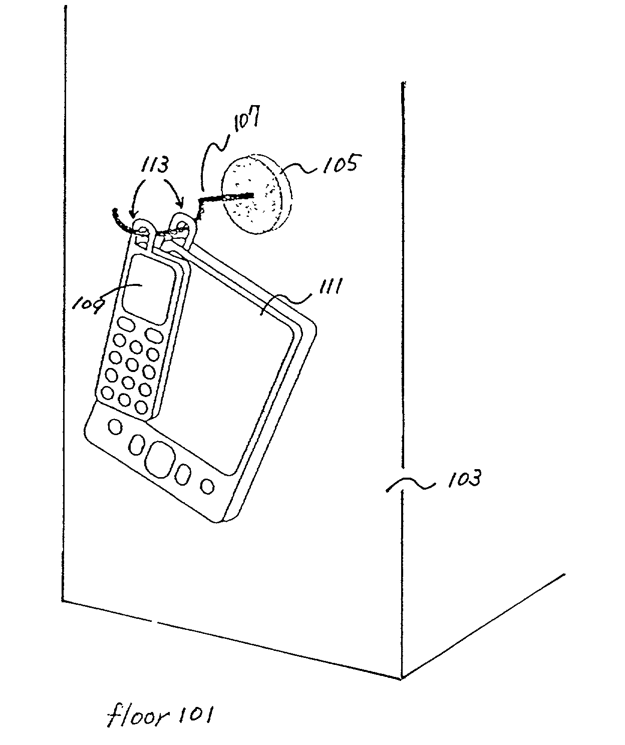
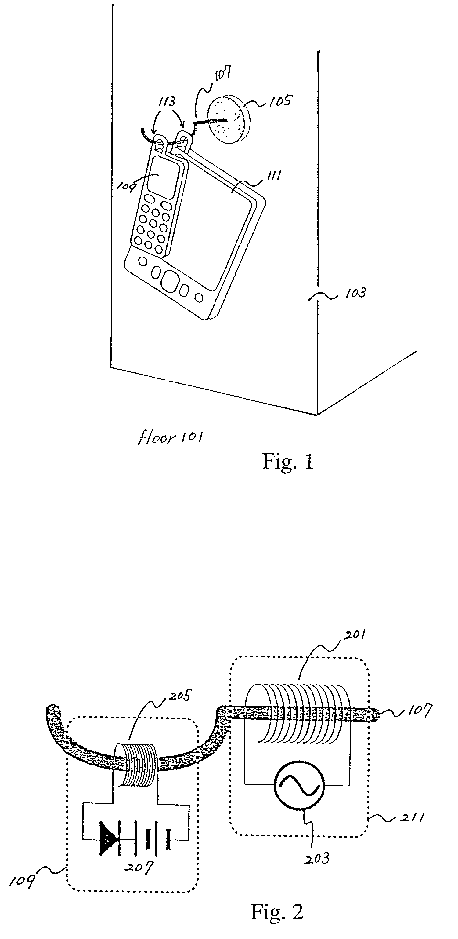
[0023]FIG. 1 is a view showing a charging system in an embodiment of the present invention as used, while FIG. 2 is an enlarged view of the interior of the charging system in the embodiment of the present invention.

[0024]As shown in FIG. 1, a wall 103 is erected perpendicularly to a floor 101 (the ground), and a charger body 105 in which a primary side coil 201 and a power feed portion 203 (shown in FIG. 2) are included is attached to the wall 103. An induction core 107 extends in the shape of a hook from the charger body 105, and penetrates through the primary side coil 201 inside the charger body 105. The induction core 107, stretching from the charger body 105, can suspend a portable telephone 109 and another portable equipment 111 through charging arches 113. Here, the charger body 105 includes a fixation member for fixing this body to the wall 103. The portable telephon...


PUM


Abstract

A wall (103 in FIG. 1) is erected perpendicularly to a floor (101), and a charger body (105) in which a primary side coil (201) and a power feed portion (203) are included is mounted on the wall (103). An induction core (107) stretches in the shape of a hook from the charger body (105), and it penetrates through the primary side coil (201) inside the charger body (105). The induction core (107) can suspend a portable telephone (109) and another portable equipment (111) through charging arches (113).

Description

BACKGROUND OF THE INVENTION[0001]1. Field of the Invention[0002]The present invention relates to a charging system, and more particularly to a charging system for portable equipment.[0003]2. Description of the Related Art[0004]A portable telephone being charged by a prior-art contactless charging system based on electromagnetic induction, is shown in FIG. 3. The portable telephone 1 includes a secondary side coil 2, while a charger 3 includes a primary side coil 7. A user sets the portable telephone 1 on the charger 3 as shown in the figure and charges it for a predetermined time, period when the remaining battery capacity of the portable telephone 1 has become small, or when the portable telephone 1 is not used for a long time.[0005]With the prior-art charging system as shown in FIG. 3, however, there is a spacing 5 between the primary side coil 7 and the secondary side coil 2, and induction cores 6 are kept apart, so that problems as mentioned below have been involved:[0006]1. Sin...

Claims


Application Information

Patent Timeline
Patent Type & Authority Patents(United States)
IPC IPC(8): H04M1/00H02J7/00H04B1/16H02J7/02H04M1/04
CPCH02J7/0027H02J7/025H04M1/04H02J7/0044H02J50/40H02J50/10H01F38/14H02J7/0042H02J2310/22H02J7/02
Inventor YAMAMOTO, TETSUYA
Owner NOKIA CORP
Why Eureka
Try Eureka