
Automatic plugging and pulling-out charging device for power battery

An automatic plug-in and charging device technology, which is applied in the direction of battery circuit devices, circuit devices, coupling devices, etc., can solve the problem of not being able to provide power batteries

Pending Publication Date: 2016-11-09
NIO NEXTEV LTD
View PDF7 Cites 18 Cited by
  • Summary
  • Abstract
  • Description
  • Claims
  • Application Information

AI Technical Summary

Problems solved by technology

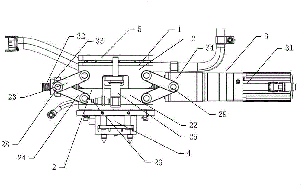
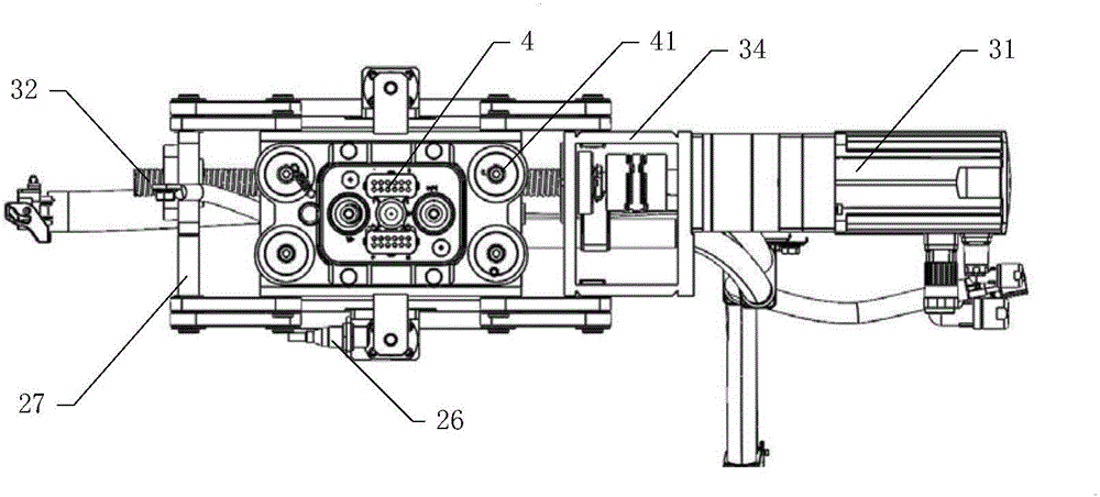
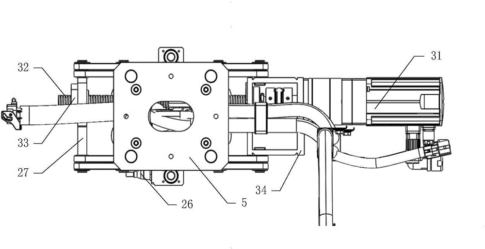
[0004] In order to solve the above-mentioned problems in the prior art, that is, in order to solve the problem that the existing charging mechanism cannot provide charging operations for the power battery with the power connector installed above and cannot realize the power battery automatically detached from the charging mechanism, the present invention provides a method for An automatic plug-in charging device for a power battery. The automatic plug-in charging device includes a fixed base, a lifting mechanism, a driving mechanism and a charging socket. The top end of the lifting mechanism is connected to the fixed base, and the bottom end of the lifting mechanism is connected to the charging socket. The socket connection, the lifting mechanism is used to make the charging socket insert or pull out the power connector of the power battery in the vertical direction, the driving mechanism is connected with the lifting mechanism, and the driving mechanism is used to drive the lifting mechanism. structural movement

Method used


Image

  • Automatic plugging and pulling-out charging device for power battery
  • Automatic plugging and pulling-out charging device for power battery
  • Automatic plugging and pulling-out charging device for power battery

Examples


Embodiment Construction

[0020] Preferred embodiments of the present invention are described below with reference to the accompanying drawings. Those skilled in the art should understand that these embodiments are only used to explain the technical principles of the present invention, and are not intended to limit the protection scope of the present invention. For example, although the charging stand in the drawings has a six-layer structure, this quantitative relationship is not static, and those skilled in the art can make adjustments to suit specific applications.

[0021] In the description of the present invention, it should be noted that the terms "center", "upper", "lower", "left", "right", "vertical", "horizontal", "inner", "outer" etc. The terms of the indicated direction or positional relationship are based on the direction or positional relationship shown in the drawings, which are only for the convenience of description, and do not indicate or imply that the device or element must have a s...


PUM


Abstract

The present invention belongs to the electric vehicle charging and discharging field and relates to an automatic plugging and pulling-out charging device for a power battery. The objective of the invention is to solve the problem that an existing charging mechanism cannot provide charging operation for a power battery and cannot make the power batter automatically disengaged from the charging mechanism. The automatic plugging and pulling-out charging device for the power battery of the invention comprises a fixing base, a lifting mechanism, a driving mechanism and a charging socket; the top end of the lifting mechanism is connected with the fixing base; the bottom end of the lifting mechanism is connected with the charging socket; the lifting mechanism is used for making the charging socket plugged into or pulled out from the power source connector of the power battery along a vertical direction; and the driving mechanism is connected with the lifting mechanism and is used for driving the lifting mechanism to move. With the automatic plugging and pulling-out charging device adopted, the automatic connection and disconnection of the power battery installed on the power source connector can be realized.

Description

technical field [0001] The invention belongs to the field of electric vehicle charging and replacing, and specifically provides an automatic plug-in and pull-out charging device for a power battery. Background technique [0002] At present, with the acceleration of the industrialization of electric vehicles, the power supply methods of electric vehicles generally include centralized charging and quick replacement of the power battery of the electric vehicle. more and more applications. However, the rapid replacement of power batteries requires corresponding charging and storage devices. The existing charging mechanism can only provide services for power batteries with power connectors installed on the side, and cannot charge power batteries with power connectors installed above. , and cannot automatically disengage from the power battery. [0003] Correspondingly, a new charging mechanism is needed in the art to solve the above problems. Contents of the invention [000...

Claims


Application Information

Patent Timeline
IPC IPC(8): H01R13/631H02J7/00
CPCH01R13/6315H01R2201/26H02J7/0045
Inventor 赵志凌朱浩侯文洁
Owner NIO NEXTEV LTD
Learn More