Charging Device, Process Cartridge, Image Forming Apparatus, And Toner

a charging device and process cartridge technology, applied in the direction of corona discharge, shaft and bearing, instruments, etc., can solve the problems of affecting the charging characteristic, the surface contamination of the charging roller increases, and the toner image remains on the charging roller, so as to maintain the charging characteristic stably, the charging roller surface is always cleaned, and the charging roller surface is cleaned.

Active Publication Date: 2007-08-23
RICOH KK
View PDF18 Cites 25 Cited by
  • Summary
  • Abstract
  • Description
  • Claims
  • Application Information

AI Technical Summary

Benefits of technology

[0026] Another object of the present invention is to provide a charging device which is equipped with a charging cleaning component which cleans the charging roller surface efficiently and maintains continuously the cleaning performance over an extended period of time, and is equipped with a charging roller which provide uniform charging of the image-supporting-medium surface stably.
[0058] According to the present invention, it is possible to provide a charging device which allows efficient cleaning of the charging roller surface, always makes the charging roller surface clean, and can maintain the charging characteristic stably by suppressing the fluctuation of the charging potential on the image supporting medium surface over an extended period of time.
[0059] Moreover, according to the process cartridge and the image forming apparatus in which the above-mentioned charging device is provided, it is possible to output a quality image stably through the uniform charging of the image-supporting-medium surface.

Problems solved by technology

However, the remaining toner which remains on the photoconductor surface after the toner image is transferred is not completely removed in the cleaning process, and such toner may reach the region in the vicinity of or in contact with the charging roller.
There is the problem that the remaining toner after the toner image transfer adheres to the charging roller.
However, the reverse charging toner and the charging roller draw each other due to the static electricity, and it easily adheres to the charging roller surface.
However, the toner having spherical particles with smaller particle diameters tends to penetrate through the cleaning blade in the cleaning process, and the penetrating toner makes the charging roller surface contamination increase further.
If the AC voltage is superimposed, the photoconductor surface will be damaged and its abrasion will increase.
However, the external additive particles with a certain hardness, such as silica particles, which are separated from the toner are easily caught by the thin Layer of the lubricant provided in the photoconductor surface.
When the photoconductor surface passes through the contact surface of the cleaning blade, the blade edge will be damaged in such a case so that the breakage and abrasion of the cleaning blade may arise.
If the abrasion of the cleaning blade progresses, the amount of the toner which passes through the cleaning blade will be increased and the charging roller surface contamination will also be increased.
However, the amount of the adhering matter that can be accumulated by such cleaning components is limited, and it is difficult to maintain the cleaning performance of the cleaning components over an extended period of time.
The use of the cleaning mechanism including the above-mentioned cleaning component is inadequate to meet the requirement.
For this reason, in the charging device of the non-contact type in which the photoconductor and the charging roller are placed in proximity with no contact, the gap between the photoconductor and the charging roller varies with the elapsed time, and the problem, such as image unevenness, takes place due to the change of the charging potential.
However, also in the image forming apparatus equipped with the charging roller constructed using the above-mentioned inelastic body, the problem of contamination of the charging roller surface by the toner penetrating through the cleaning blade which contacts the photoconductor arises similarly.

Method used


Image

  • Charging Device, Process Cartridge, Image Forming Apparatus, And Toner
  • Charging Device, Process Cartridge, Image Forming Apparatus, And Toner
  • Charging Device, Process Cartridge, Image Forming Apparatus, And Toner

Examples


example 2

of Charging Roller

[0276] The resistance of the protection layer is 4×10¹⁰ ohm-cm, and the thickness is about 10 micrometers. The resistance adjustment layer was formed by covering with injection molding the composite which blended and created the high molecular compound (“reorekkusu A-1720” from “dai-ichi kogyo seiyaku” Co.) 30 weight parts of ion conductivity which contains the fourth class ammonium-salt group to the ABS-plastics (“GR-1500” from “denki kagaku kogyo” Co.) 100 weight parts to the peripheral surface of the roller base made from stainless steel with a diameter of 8 mm. The volume resistivity value of the composite is 1×10⁸ ohm-cm.

[0277] Next, the charging roller (2) with a diameter of 12 mm is produced by applying to the surface of the resistance adjustment layer the mixture which includes the polyamide resin (“daiamido T-171” from “daiseruhyurusu” Co.) and the carbon black (it is the 10% of the weight to the total solid), and forming the protection layer in it. The ...

example 1

of Charging Cleaning Component

[0278] The charging cleaning component the periphery side of the example 1 of 5-mm diameter core metal is made to carry out heating compression of the layer which includes the melamine resin foam (“basotekuto” from BASF A.G.) , and it sticks on it with adhesive. After the adhesion, the charging cleaning component (1) of the profile of roller with an outside diameter of 8.5 mm is produced by forming so that it may become 1.75 mm in thickness by carrying out the barrel polishing.

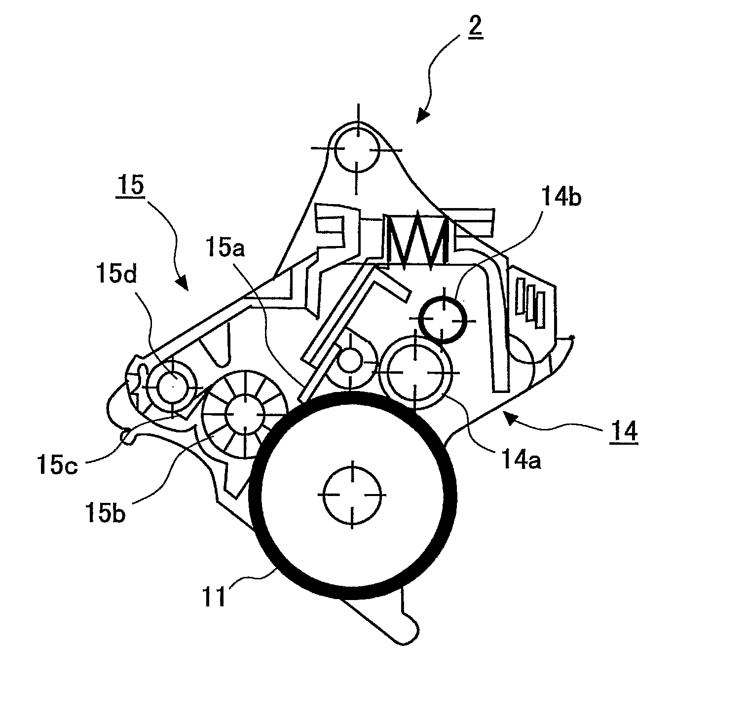
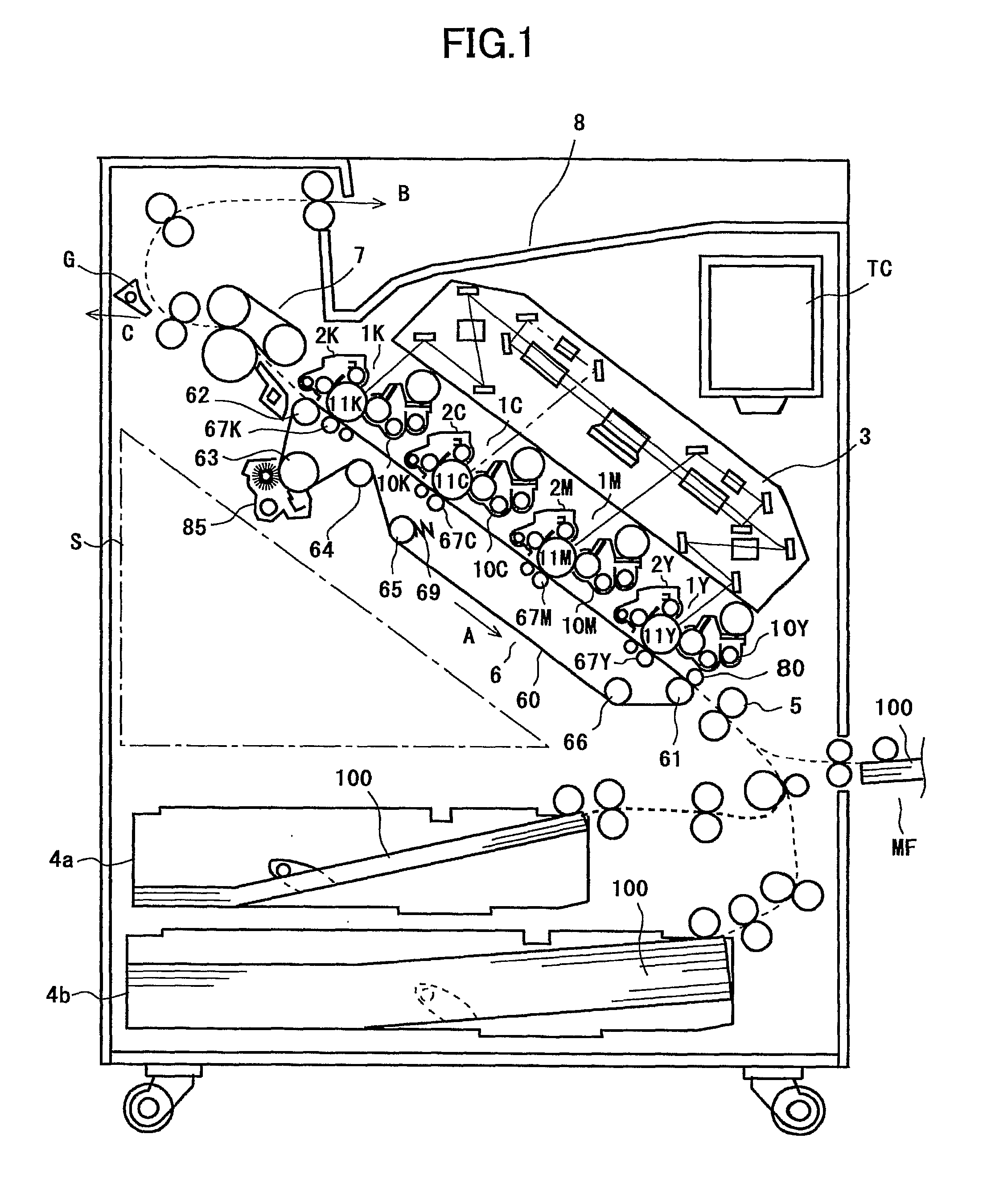
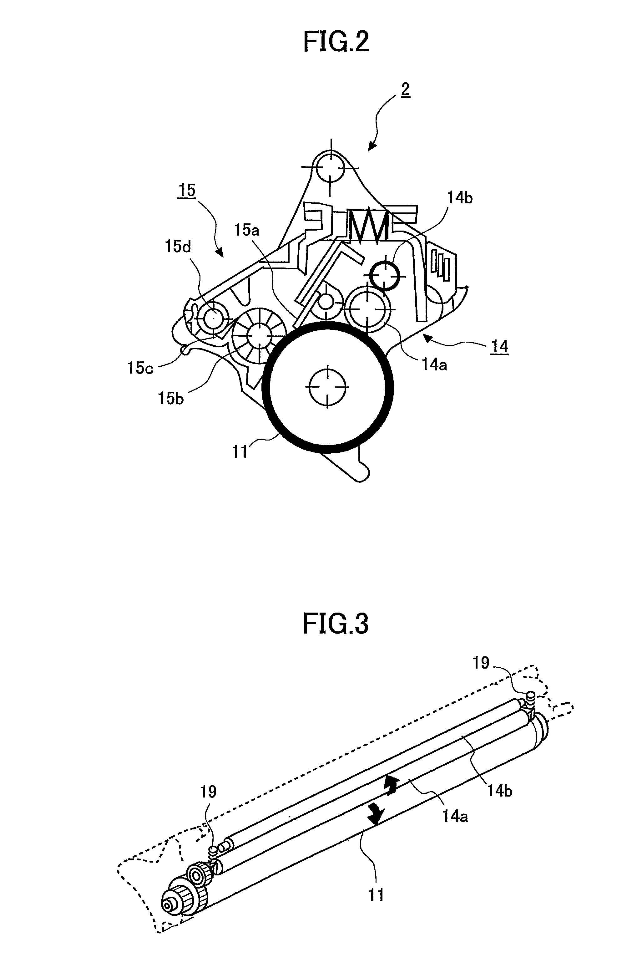
[0279] Next, the charging roller (1) produced as mentioned above by the group as shown in FIG. 1 as charging roller 14a, or (2) are disposed. The charging cleaning component (1) is disposed as the charging cleaning component 14b. The spacer tape is stuck on the non-image region of the shaft-orientations both ends of charging roller 14a.

[0280] The charging roller 14a is installed such that the gap between the charging roller 14a and the photoconductor drum 11 is set to 50 microme...


PUM


Abstract

The present invention provides a charging device which comprises a charging roller (14a) and a cleaning component (14b). The charging roller charges a surface of an image-recording medium (11) with a voltage which is applied from an external source. The cleaning component cleans a surface of the charging roller. The charging roller includes a resistance adjustment layer which is made of a resin composite and formed on an outer periphery of a core metal. The hardness of the charging roller is 45 degrees or more in JIS D hardness. The cleaning component has a portion which is in contact with the charging roller This portion is made of resin foam which has a continuous foam structure. The density of the resin foam is 5 to 15 kg / m3 and its tensile strength is 1.7±0.5 kg / cm2.

Description

TECHNICAL FIELD [0001] The present invention relates to a charging device and a process cartridge and an image forming apparatus equipped with the charging device, in which charging processing to the image supporting medium is performed in the image forming apparatus of electrophotographic printing type, such as the copier, the laser printer, and the facsimile. BACKGROUND ART [0002] In the image forming apparatus of electrophotographic printing type, the surface of the photoconductor which is the image supporting medium is subjected to the charging processing by applying the charge of a predetermined polarity by the discharging, and the charged photoconductor surface is exposed to light so that an electrostatic latent image is formed. The toner which is charged with the same polarity as in the charging processing is supplied to this electrostatic latent image, and the toner image is formed. After that, the toner image formed on the photoconductor is transferred to the recording pape...

Claims


Application Information

Patent Timeline
Patent Type & Authority Applications(United States)
IPC IPC(8): G03G15/02G03G9/08F16C13/00G03G9/087G03G21/10G03G21/18
CPCG03G15/0225G03G15/0216G03G15/0233G03G15/06
Inventor MIZUISHI, HARUJIOJIMI, TOKUYAKOIKE, TOSHIOSHINTANI, TAKESHIARAI, YUJIYONEDA, TAKUZIAMEMIYA, KENTAWADA, TAKAAKITOMITA, MASAMIKAWASUMI, MASANORIMURAISHI, TAKAYAHARADA, HIROOMININOMIYA, HIROMICHI
Owner RICOH KK
Why Eureka
Try Eureka