Systems and methods for pulse rotation modulation encoding and decoding

a pulse rotation and modulation technology, applied in the field of communication systems, can solve the problems of reducing the aggregate channel efficiency to significantly less than that of a non-shared spectrum, channel capacity underutilized, and the fdma communication system does not provide a significant improvement in the security of the waveform

Active Publication Date: 2012-12-27
HARRIS CORP
View PDF3 Cites 11 Cited by
  • Summary
  • Abstract
  • Description
  • Claims
  • Application Information

AI Technical Summary

Benefits of technology

[0019]According to other aspects of the present invention, the respective portion of the first data comprises one more data characters, such as binary encoded data bits. The bits can represent, but are not limited to, text, sound, pictures, navigational-position information, and/or any other types of useful payload information that can be communicated. Moreover, the data characters may be chosen ...

Problems solved by technology

In practice, implementation trade offs and coordination of communications between the users in the MA communication system (each of which practically have different channels) reduce the aggregate channel efficiency to significantly less than that of a non-shared spectrum.
Moreover, there may not be enough users in the channel at one time to fully use the spectrum, which leaves channel capacity underutilized.
However, the FDMA communication system does not provide a significant improvement in the security of the waveform as compared to that of other communication systems since the instantaneous energy density of a channel in use is relatively high.
Still, the detection characteristics of the frequency hopping FDMA communication systems are not significantly improved over non-frequency hopping FDMA communication systems.
Although DSSS based CDMA communication systems improved the security of transmiss...

Method used


Image

  • Systems and methods for pulse rotation modulation encoding and decoding
  • Systems and methods for pulse rotation modulation encoding and decoding
  • Systems and methods for pulse rotation modulation encoding and decoding

Examples


Embodiment Construction

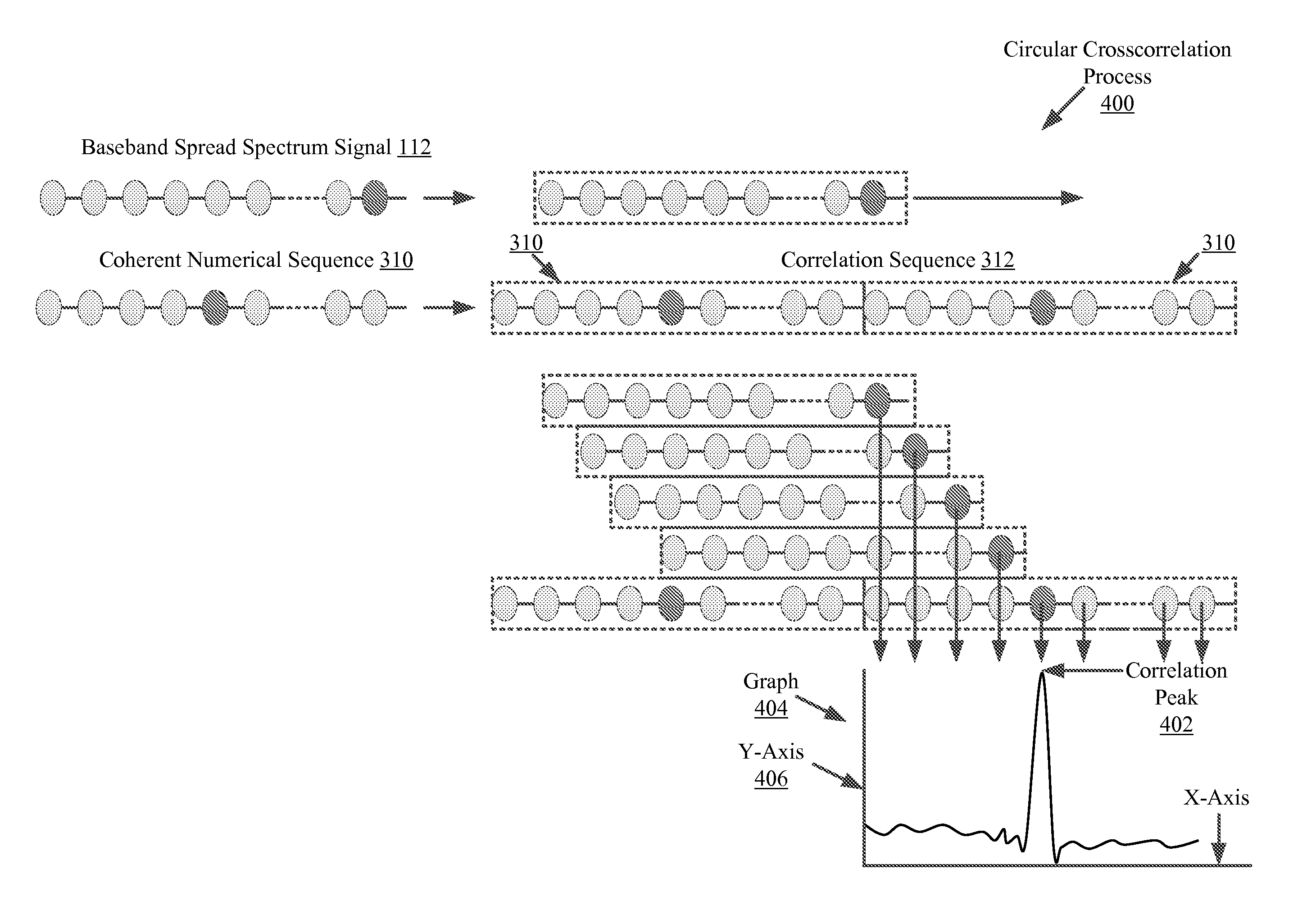
[0029]The present invention is described with reference to the attached figures. The figures are not drawn to scale and they are provided merely to illustrate the instant invention. Several aspects of the invention are described below with reference to example applications for illustration. It should be understood that numerous specific details, relationships, and methods are set forth to provide a full understanding of the invention. One having ordinary skill in the relevant art, however, will readily recognize that the invention can be practiced without one or more of the specific details or with other methods. In other instances, well-known structures or operation are not shown in detail to avoid obscuring the invention. The present invention is not limited by the illustrated ordering of acts or events, as some acts may occur in different orders and / or concurrently with other acts or events. Furthermore, not all illustrated acts or events are required to implement a methodology i...


PUM


Abstract

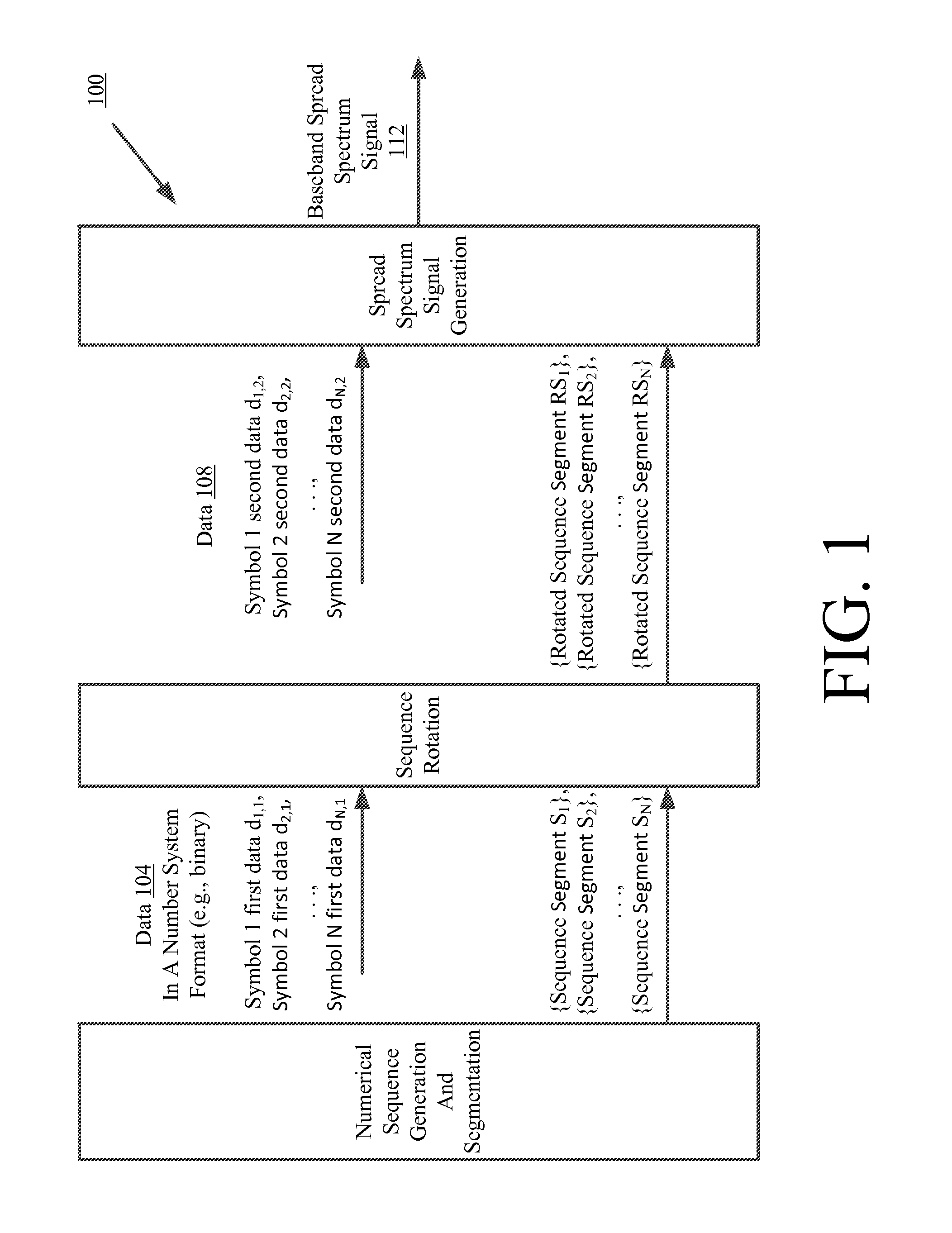
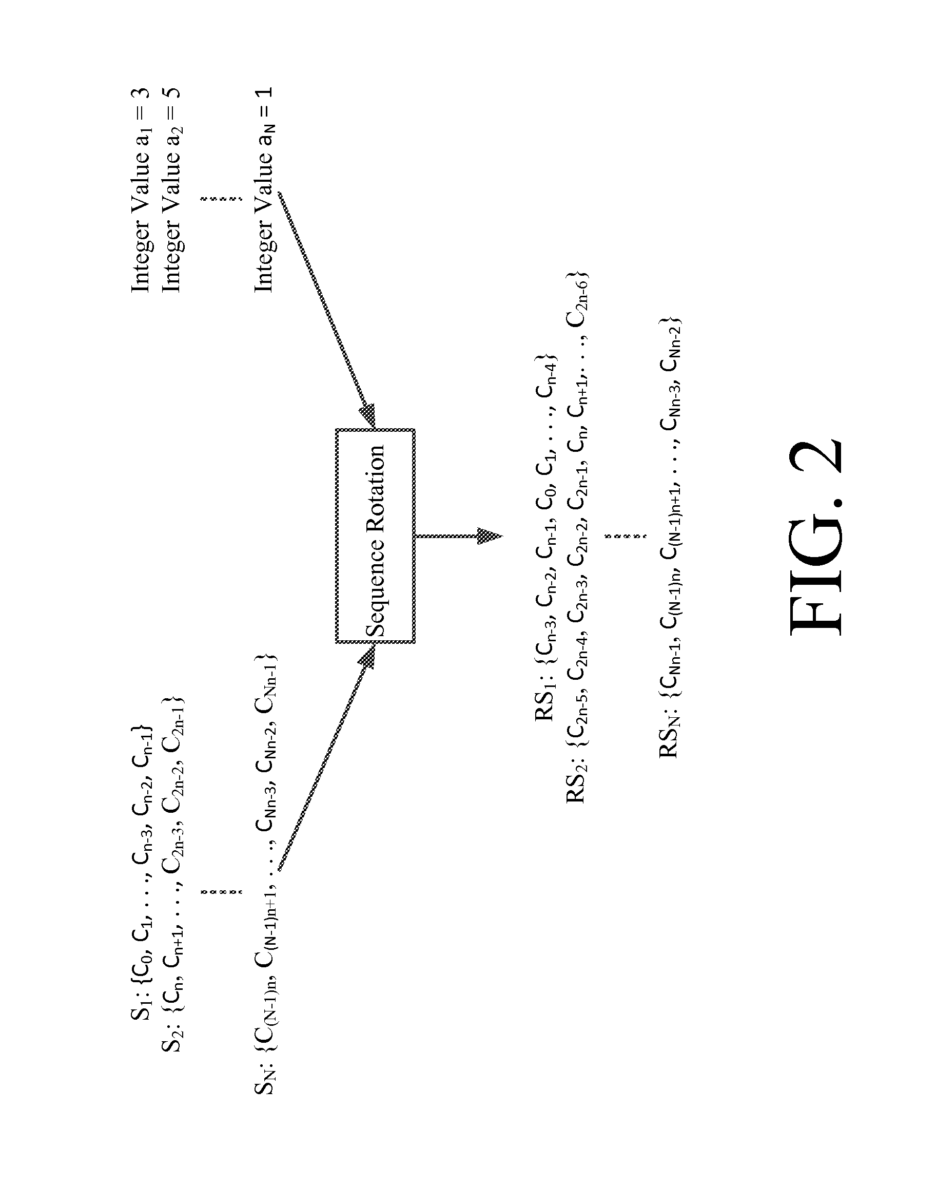
Systems (600) and methods (500) for Pulse Rotation Modulation. The methods involve: generating First Segments (“FSs”) of a Numerical Sequence (“NS”) based on a First Data Symbol Sequence (“FDSS”); and encoding FDSS within NS. The encoding is achieved by: (a) shifting positions of numbers contained in each FS “X” positions to the right or left; and (b) moving a last “X” numbers of the FSs to a beginning of a respective segment thereof or moving a first “X” numbers of the FSs to an end of the respective segment. X” is defined as an integer value represented by a respective portion of FDSS. Thereafter, the NS having FDSS encoded therein can be used to spread a Second Data Signal (“SDS”) over a wide intermediate frequency band. SDS has second data symbols, that are different then FDSS, phase and/or amplitude encoded therein.

Description

BACKGROUND OF THE INVENTION[0001]1. Statement of the Technical Field[0002]The invention concerns communication systems. More particularly, the invention concerns communications systems in which phase rotation modulation encoding and decoding are performed.[0003]2. Description of the Related Art[0004]There are many spread spectrum communication systems known in the art. Such spread spectrum communication systems often employ modulation techniques to encode data at baseband, while spread spectrum techniques permit a system to increase bandwidths of the transmitted signals and lower the power spectral density, effectively spreading the signal energy. Such baseband modulation techniques include Frequency Shift Keying (“FSK”) modulation techniques, Phase Shift Keying (“PSK”) techniques, Pulse Amplitude Modulation (“PAM”) techniques, Phase Shift Keying Modulation (“PSK”) techniques and On Off Keying (“00K”) techniques. Each of the listed modulation techniques are well known in the art, an...

Claims


Application Information

Patent Timeline
IPC IPC(8): H04B1/7073
CPCH04J13/0074H04B1/707
Inventor MICHAELS, ALAN J.
Owner HARRIS CORP
Why Eureka
Try Eureka