Intraosseous nerve denervation methods

a technology of intraosseous nerves and curved paths, which is applied in the field of creating curved paths in bone, can solve the problems that the curved channels within the varying density cancellous bone will generally not predictably or accurately support and contain the treatment devi

Inactive Publication Date: 2012-12-27
RELIEVANT MEDSYST
View PDF6 Cites 59 Cited by
  • Summary
  • Abstract
  • Description
  • Claims
  • Application Information

AI Technical Summary

Benefits of technology

[0016]In another aspect of the present invention, a tube-within-tube embodiment has a deployable curved Nitinol tube that deploys from a straight cannula. The Nitinol tube is pre-curved to create an angular range of approximately 0° to approximately 180°, but more specifically from approximately 45° to approximately 110°, when fully deployed from the straight cannula. The design of the curve is such that the flexible element (carrying the treatment device) can navigate through the angular range of deployment of the nitinol tube. The curved nitinol tube allows the flexible element to navigate through a curve within bone without veering off towards an unintended direction. Cancellous bone density varies from person to person. Therefore, creating a curved channel within varying density cancellous bone will generally not predictably or accurately support and contain the treatment device as it tries to navigate the curved channel. With the present invention, the flexible element is deployed into the bone through the curved Nitinol tube, which supports the element as it traverses through the curve. When it departs from the tube, it will do so in a linear direction towards the target zone. This design allows the user to predictably and accurately deploy the flexible element towards the target zone regardless of the density of the cancellous bone.

Problems solved by technology

Therefore, creating a curved channel within varying density cancellous bone will generally not predictably or accurately support and contain the treatment device as it tries to navigate the curved channel.

Method used


Image

  • Intraosseous nerve denervation methods
  • Intraosseous nerve denervation methods
  • Intraosseous nerve denervation methods

Examples


first embodiment

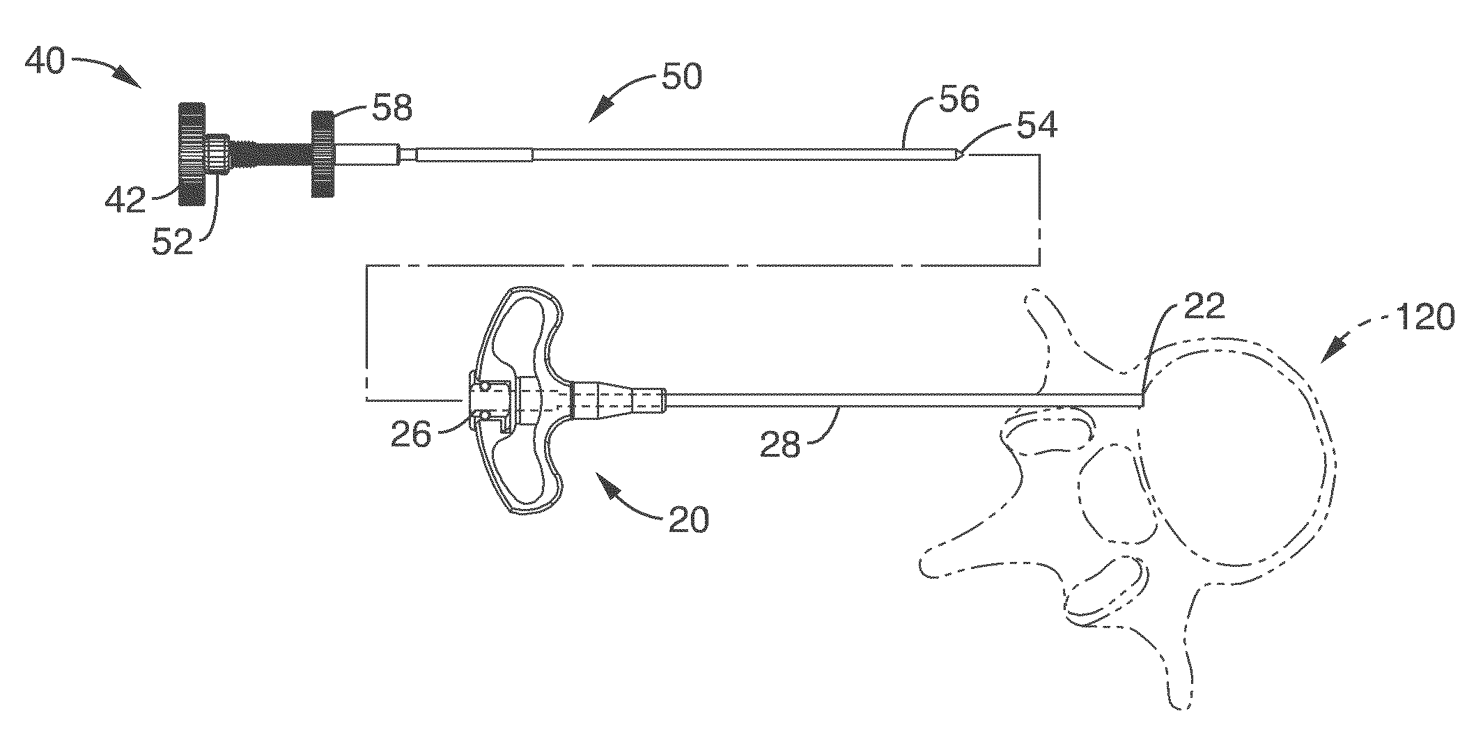
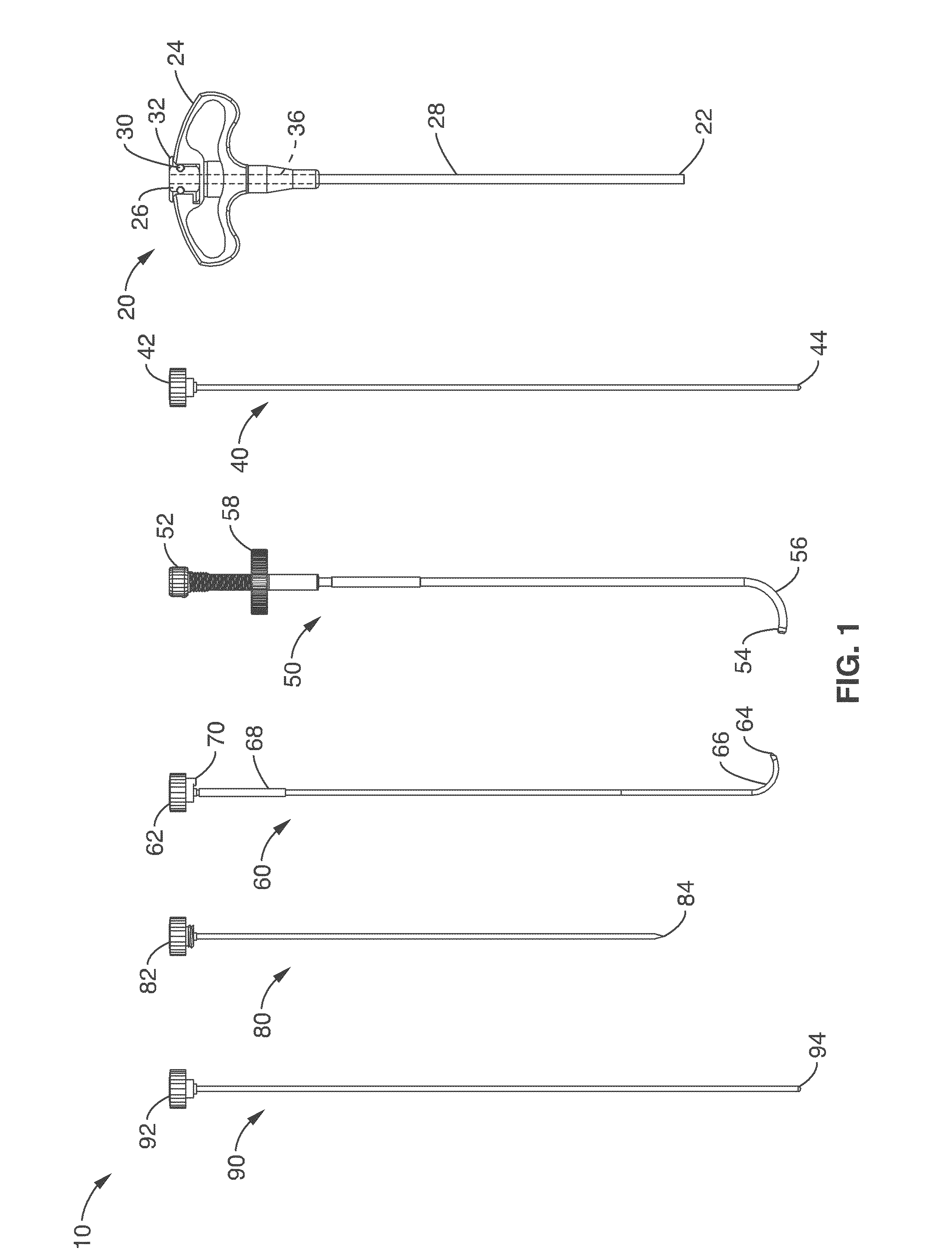
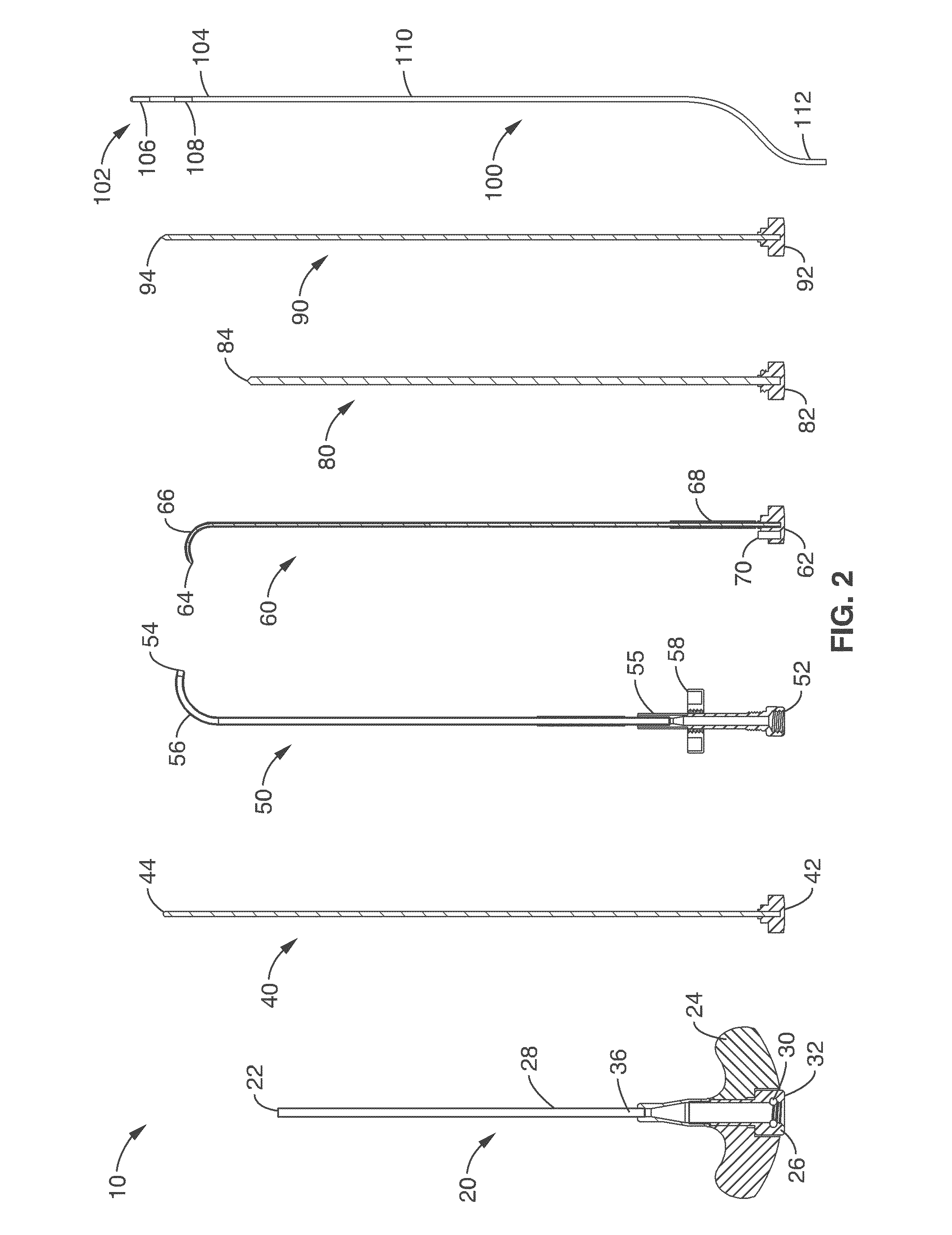
[0064]FIGS. 1 and 2 illustrate the present invention comprising a system or kit 10 for forming a path through bone. The system comprises a having a needle trocar 20 (the main body of the instrument set). The trocar 20 comprises an elongate shaft 28 having a handle 24 at its proximal end 32 and a central lumen 36 passing through to the distal end 22 of the trocar 20. The central lumen 36 is generally sized to allow the other instruments in the system 10 to be slideably introduced into the patient to a treatment region. System 10 further comprises a straight stylet 80 having a sharp-tipped needle 84 at its distal end that is used with the needle trocar 20 to create the initial path through the soft tissue and cortical shell to allow access to the cancellous bone, a curved cannula 50 that is used to create / maintain the curved path within the bone / tissue. A straightening stylet 40 is used to straighten out the curve and load the curved cannula 50 into the needle trocar 20. A curved styl...

embodiment 1

[0137]2. A system , wherein the trocar further comprises a sharp distal tip configured to pierce through bone to generate a linear path through bone.

embodiment 2

[0138]3. A system , wherein the curveable cannula comprises a sharpened distal tip configured to pierce through bone to generate a curved path extending from a linear path generated by the trocar.

[0139]4. A system according to embodiment 1, wherein the distal end of the curveable cannula is deformable so as to be delivered in a straight configuration through the trocar and deployed in a curved configuration outward from the radial opening at an angle with respect to the central axis.


PUM


Abstract

System and methods for channeling a path into bone include a trocar having a proximal end, distal end and a central channel disposed along a central axis of the trocar. The trocar includes a radial opening at or near the distal end of the trocar. The system includes a curveable cannula sized to be received in the central channel, the curveable cannula comprising a curveable distal end configured to be extended laterally outward from the radial opening in a curved path extending away from the trocar. The curveable cannula has a central passageway having a diameter configured allow a probe to be delivered through the central passageway to a location beyond the curved path.

Description

CROSS-REFERENCE TO RELATED APPLICATIONS[0001]This application is a continuation of International Application No. PCT / US2011 / 20535 filed on Jan. 7, 2011. This application is also a continuation of U.S. application Ser. No. 12 / 868,818 filed on Aug. 26, 2010, which is a continuation of U.S. application Ser. No. 12 / 683,555 filed on Jan. 7, 2010, which is a continuation-in-part of U.S. application Ser. No. 12 / 566,895 filed on Sep. 25, 2009, which claims the benefit of U.S. Provisional No. 61 / 100,553 filed on Sep. 26, 2008. U.S. application Ser. No. 12 / 683,555 is also a continuation-in-part of U.S. application Ser. No. 11 / 123,766 filed on May 6, 2005, now U.S. Pat. No. 7,749,218, which is a divisional of U.S. application Ser. No. 10 / 260,879 filed on Sep. 30, 2002, now U.S. Pat. No. 6,907,884. The entire contents of each of the above-listed applications are hereby expressly incorporated by reference herein.STATEMENT REGARDING FEDERALLY SPONSORED RESEARCH OR DEVELOPMENT[0002]Not ApplicableI...

Claims


Application Information

Patent Timeline
Patent Type & Authority Applications(United States)
IPC IPC(8): A61B18/18A61B18/04
CPCA61B17/3472A61B17/8805A61B18/02A61B18/148A61B18/16A61B17/1671A61B2018/00017A61B17/32002A61B2017/00261A61B2017/00331A61B2017/00867A61B18/18A61B17/8811A61B17/8819A61B2018/2244A61B17/3415A61B18/1492A61B2018/0044A61B2018/00577A61B2018/126A61N7/00
Inventor PELLEGRINO, RICHARDPAPINEAU, PAULACROMBIE, JOHN S.PATEL, SAMITRYAN, THOMAS
Owner RELIEVANT MEDSYST
Why Eureka
Try Eureka