Air-conditioning apparatus

Active Publication Date: 2013-01-03
MITSUBISHI ELECTRIC CORP
View PDF1 Cites 15 Cited by
  • Summary
  • Abstract
  • Description
  • Claims
  • Application Information

AI Technical Summary

Benefits of technology

[0010]In the air-conditioning apparatus according to the invention, if the refrigerant flow velocity at the outlet side of the radiator is lower than the predetermined threshold value, the refrigerant flow velocity at the outlet side of the radiator is increased by the flow control means so that the oil-return operation for re

Problems solved by technology

This would hind

Method used


Image

  • Air-conditioning apparatus
  • Air-conditioning apparatus
  • Air-conditioning apparatus

Examples


embodiment 1

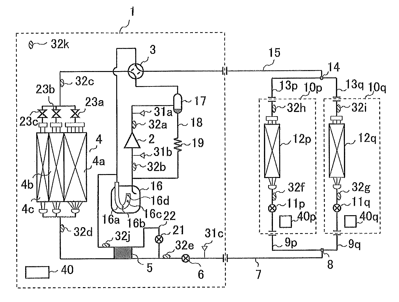
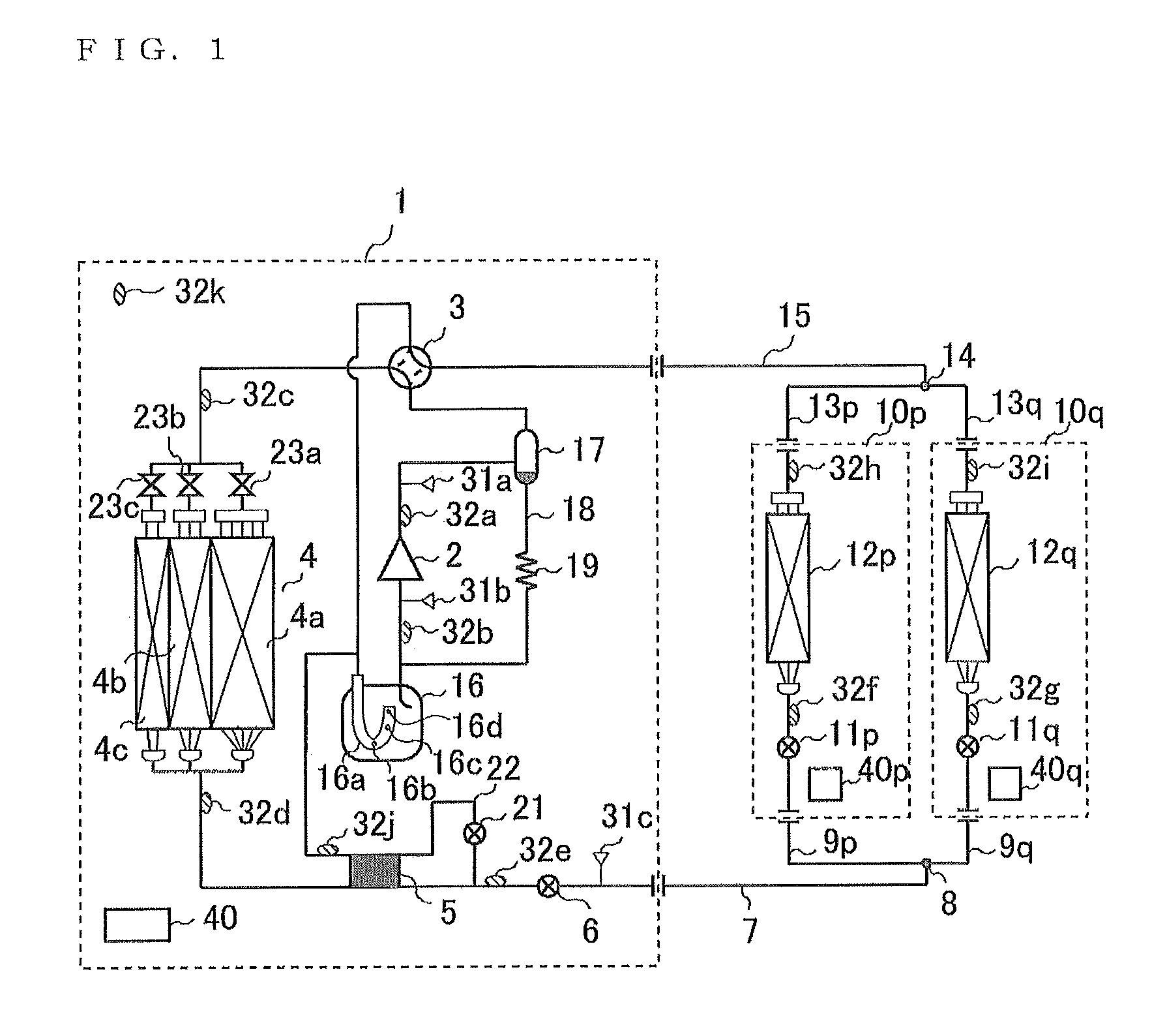
[0020]FIG. 1 shows a refrigerant circuit diagram of an air-conditioning apparatus according to Embodiment 1 of the invention. Embodiment 1 of the invention will be described below.

[0021]In FIG. 1, reference numeral 1 denotes an outdoor unit, 10p and 10q denote indoor units, 15 denotes a main gas piping connected to the outdoor unit 1, 13p and 13q denote gas branch pipings connected to the indoor units 10p and 10q, 14 denotes a junction point between the main gas piping 15 and the gas branch pipings 13p and 13q, 7 denotes a main liquid piping connected to the outdoor unit 1, 9p and 9q denote liquid branch pipings connected to the indoor units 10p and 10q, and 8 denotes a junction point between the main liquid piping 7 and the liquid branch pipings 9p and 9q.

[0022]In the outdoor unit 1, an oil separator 17 and a four-way valve 3 for switching flow paths are provided on the discharge side of a compressor 2. Reference numerals 4a, 4b, and 4c denote heat-exchanger paths having different...


PUM


Abstract

In an air-conditioning apparatus that uses a refrigerant, which operates in a transcritical cycle, and refrigerating machine oil, which has low miscibility with the refrigerant, in a refrigerant circuit for a refrigeration cycle connected to a compressor, a radiator, an expansion mechanism, and an evaporator, the air-conditioning apparatus includes a flow regulating mechanism provided in the refrigerant circuit, and flow control means that controls the flow regulating mechanism. If a refrigerant flow velocity at an outlet side of the radiator is lower than a predetermined threshold value, the refrigerant flow velocity at the outlet side of the radiator is increased by the flow control means so that oil-return operation that returns the refrigerating machine oil discharged from the compressor to the compressor is performed for at least a predetermined time period.

Description

TECHNICAL FIELD[0001]The present invention relates to an oil-return process performed when refrigerating machine oil discharged from a compressor accumulates in a radiator in an air-conditioning apparatus in which a cycle becomes a transcritical cycle.BACKGROUND ART[0002]In an air-conditioning apparatus of the related art that uses a fluorocarbon refrigerant, refrigerating machine oil that is readily soluble in a liquid refrigerant having miscibility therewith is used. This is particularly typical when used for the purpose of air conditioning a building, in which the refrigeration cycle is large-scaled and complicated, because it is advantageous in that the refrigerating machine oil is less likely to accumulate in areas where the liquid refrigerant exists within the cycle.[0003]However, with a recent trend towards the use of natural refrigerants, such as carbon dioxide, mechanical components, such as a compressor, require refrigerating machine oil with high viscosity. High-viscosity...

Claims


Application Information

Patent Timeline
IPC IPC(8): F25B49/02F25B41/00
CPCF25B31/004F25B2309/061F25B2600/2513Y02B30/741F25B9/008F25B2600/0253F25B2600/2519Y02B30/70F25B2500/16
Inventor SHIMAZU, YUSUKETAKAYAMA, KEISUKEHATOMURA, TAKESHI
Owner MITSUBISHI ELECTRIC CORP
Why Eureka
Try Eureka