Universal gasoline engine fuel tank cover

a gasoline engine and fuel tank cover technology, applied in the field of universal gasoline engine fuel tank cover, can solve the problems of increased manufacturing cost, complicated assembly, fuel wastage and environmental pollution, etc., and achieve the effects of simple structure design, reduced swaying movement, and easy assembly

Active Publication Date: 2013-01-03
CHONGQING ZONGSHEN GENERAL POWER MACHINE
View PDF13 Cites 13 Cited by
  • Summary
  • Abstract
  • Description
  • Claims
  • Application Information

AI Technical Summary

Benefits of technology

[0014]The outer shell is disposed with projected ribs on the inner wall thereof to ensure connection between the air hole II and the atmosphere. The distance between the ribs and the limiting circumference is very small or there is zero clearance between them, and this reduces the swaying movement between the inner shell and the outer shell.
[0015]A foam cover is disposed between the fine carbon particles in the first absorption chamber and the second absorption chamber and the lower surface of the sealing cover. The foam cover is adequately compressed and deformed by the sealing cover, and the fine carbon particles are adequately compressed in the first and second absorption chambers to prevent the fine carbon particles from being swayed between the first and second absorption chambers and the sealing cover.
[0016]The present utility model is advantageous in that it has a delicate structural design, it is easy to assemble, its cost is low, it can effectively prevent direct exhaust of volatilized gasoline into the atmosphere, and accurate judgment can be made as to whether the fuel tank cover is adequately tightened.

Problems solved by technology

In addition, when the universal engine is excessively tilted or inclined, gasoline in the fuel tank will still flow out through this ventilation channel, and this does not only cause fuel wastage but also environmental pollution.
However, as carbon canisters and pour valves are separate parts, assembly is made complicated and manufacturing cost is increased.

Method used


Image

  • Universal gasoline engine fuel tank cover
  • Universal gasoline engine fuel tank cover
  • Universal gasoline engine fuel tank cover

Examples


Embodiment Construction

[0024]The present utility model will be further illustrated in connection with the drawings by the following embodiment which shall not be construed as limiting, and any improvement or substitution based on the spirit of the present utility embodiment would still fall within the scope of the claims defining the utility model.

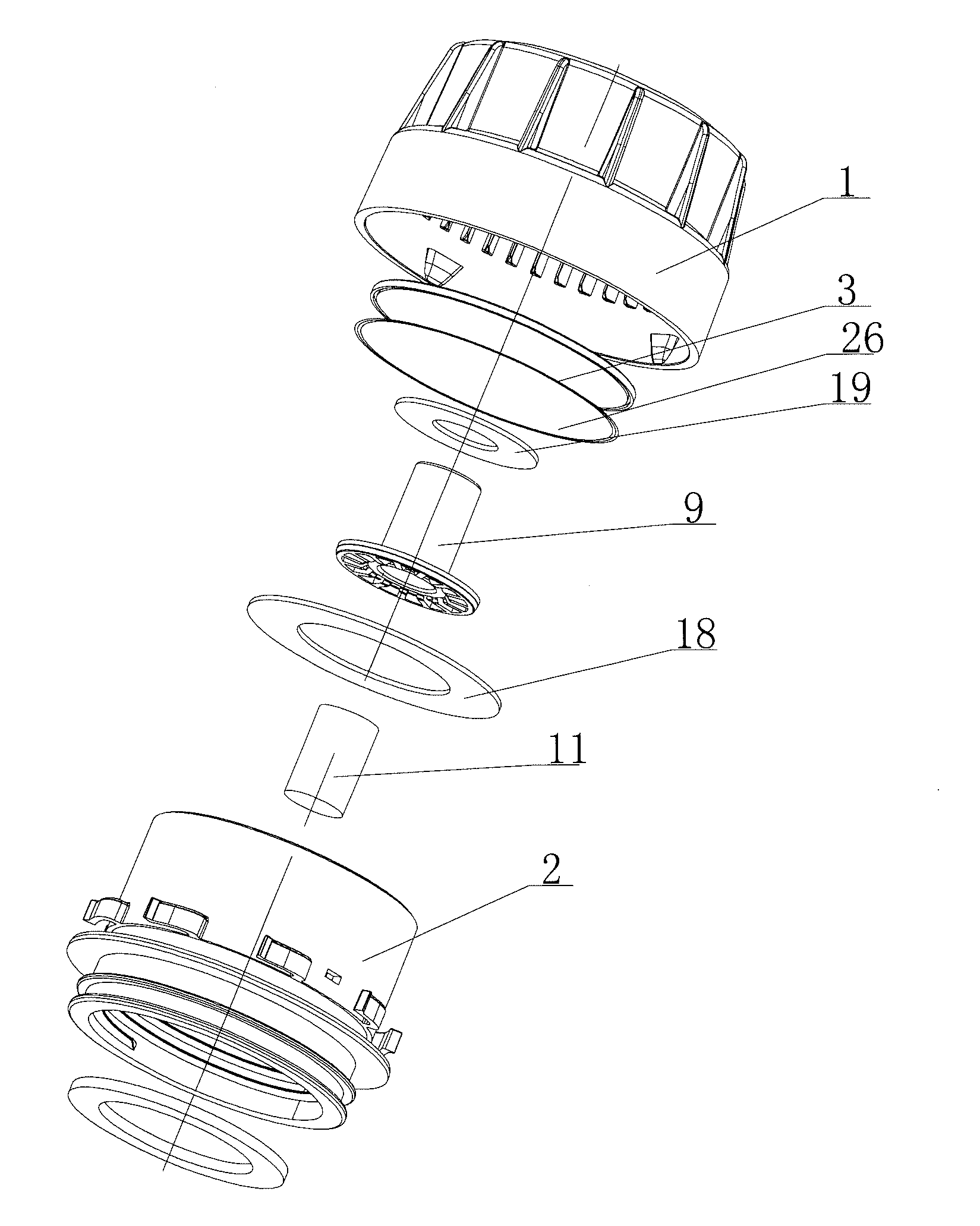
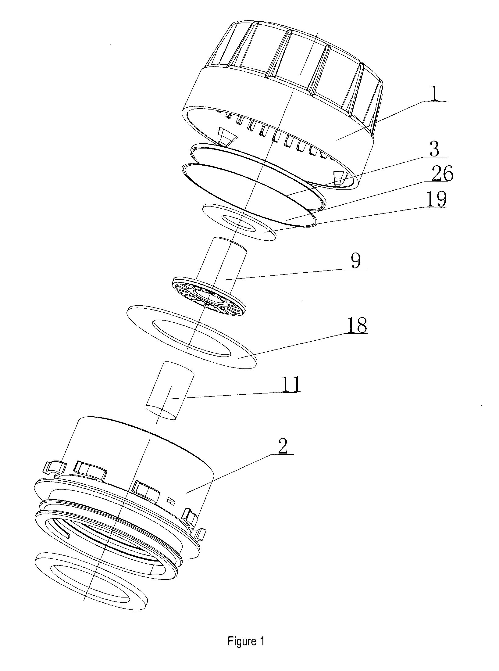
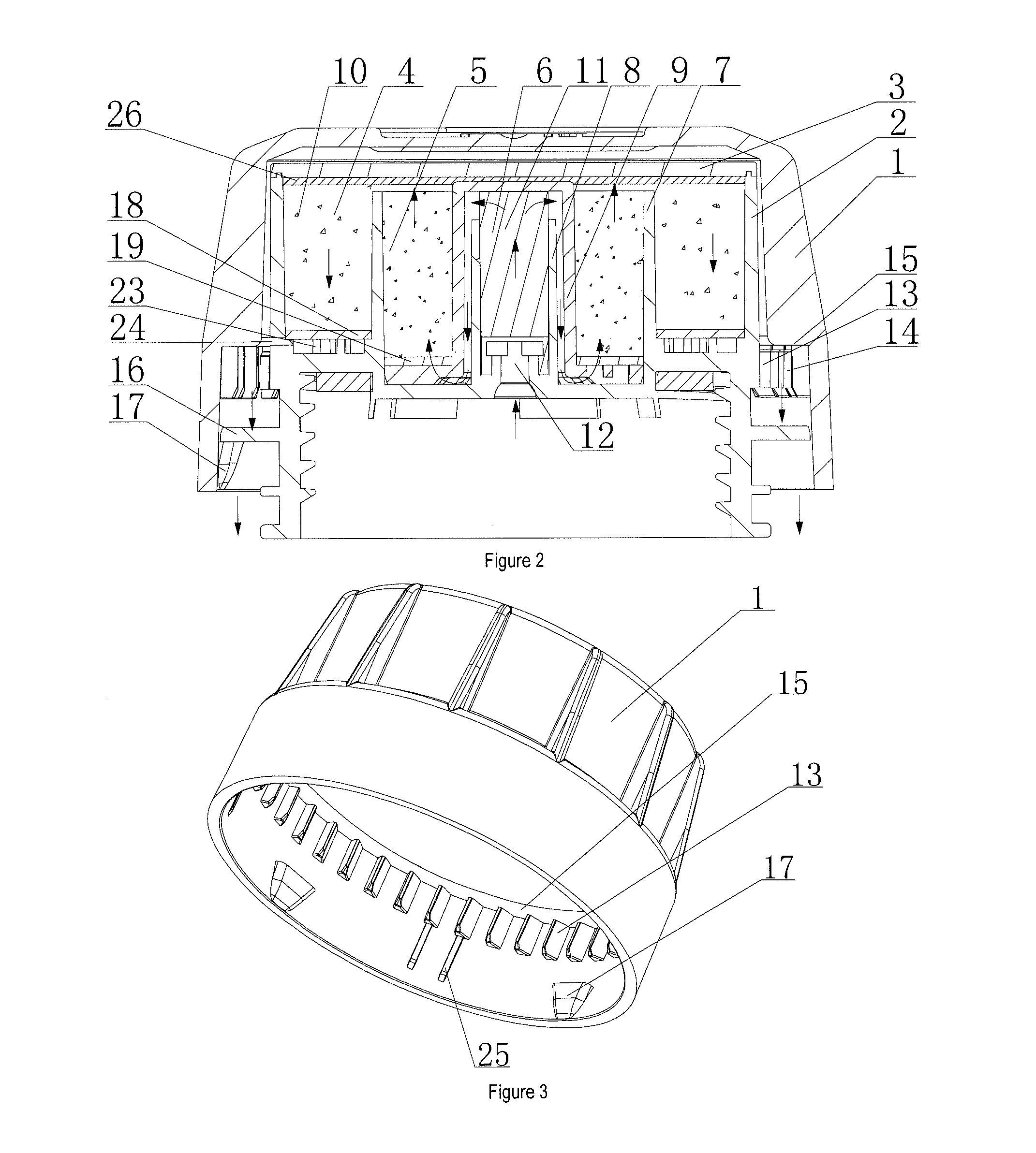
[0025]FIGS. 1 and 2 illustrate a universal gasoline engine fuel tank cover, comprising an outer shell (1), an inner shell (2) and a sealing cover (3) located on the upper surface of the inner shell (2), wherein the outer shell (1) and the inner shell (2) are connected through a ratchet mechanism and a limiting mechanism for torsional control, the inner shell (2) having a partition I (7) and a partition II (8) disposed in its upper cavity to divide the upper cavity inwardly into a first adsorption chamber (4), a second adsorption chamber (5) and a third adsorption chamber (6), the partition I (7) and the sealing cover (3) having a ventilation clearance disposed t...


PUM

PropertyMeasurementUnit
heightaaaaaaaaaa
distanceaaaaaaaaaa
circumferenceaaaaaaaaaa

Abstract

The present utility model discloses a universal gasoline engine fuel tank cover including an outer shell, an inner shell and a sealing cover located on the upper surface of the inner shell, wherein the outer shell and the inner shell are connected through a ratchet mechanism and a limiting mechanism, the inner shell having a partition I and a partition II disposed in its upper cavity to divide the upper cavity into a first adsorption chamber, a second adsorption chamber and a third adsorption chamber, the first adsorption chamber and the second adsorption chamber having fine carbon particles disposed therein, the third adsorption chamber having a cylindrical foam disposed therein, the bottom of the partition I being disposed with an air hole I connecting the third adsorption chamber to the fuel tank, and the bottom of the first adsorption chamber being disposed with an air hole II causing the first adsorption chamber to be connected to the atmosphere outside. The present utility model is advantageous in that it has a delicate structural design, it is easy to assemble, its cost is low, it can effectively prevent direct exhaust of volatilized gasoline into the atmosphere, and accurate judgment can be made as to whether the fuel tank cover is adequately tightened.

Description

FIELD[0001]The present utility model relates generally to a universal gasoline engine and, more particularly, to a universal gasoline engine fuel tank cover.BACKGROUND[0002]An existing universal gasoline engine fuel tank cover mainly comprises an outer shell, a card lock pedestal, a plastic disc, a card lock slice and a fuel tank inner cover. The outer shell and the card lock pedestal are riveted and a plastic disc is supported between the card lock pedestal and the outer shell, the plastic disc has a fuel tank inner cover disposed in the bottom cavity thereof, the card lock pedestal has a card lock slice connected to the bottom thereof, the plastic disc has a plurality of projected ribs disposed at the top portion thereof, the projected ribs being disposed with air gaps thereon, the plastic disc, fuel tank inner cover, card lock pedestal and card lock slice being respectively disposed with ventilation holes, and the fuel tank inner cavity being connected to the atmosphere through t...

Claims


Application Information

Patent Timeline
Patent Type & Authority Applications(United States)
IPC IPC(8): B65D51/00B65D41/02B65D51/24B65D51/16
CPCF02M25/0854B60K15/0406B60K2015/0451B60K2015/0441B01D2259/4516B01D2253/102B01D2257/702B01D2259/41B01D53/0407
Inventor WANG, YICHAOLI, HUARONGPEI, JUNJIE
Owner CHONGQING ZONGSHEN GENERAL POWER MACHINE
Why Eureka
Try Eureka