Sensor device

A technology for sensor devices and sensor housings, applied to measuring devices, instruments, devices using electric/magnetic methods, etc., can solve problems such as the influence of reading accuracy, signal distortion, and the difficulty of accurately estimating angular position and rotational speed. Achieve the effect of simple signal valuation

Inactive Publication Date: 2012-11-14
LENORD BAUER & CO
View PDF3 Cites 0 Cited by
  • Summary
  • Abstract
  • Description
  • Claims
  • Application Information

AI Technical Summary

Problems solved by technology

[0005] This distorts the generated signal and makes accurate estimation of angular position and rotational speed difficult
In the case of small eccentricities in the case of small oscillating movements of the shaft, which may be due to mechanical tolerances in production or due to the type of bearing, the reading accuracy in operation is affected and therefore a natural limit is set for the angle determination
Compensation of mechanically determined tolerances (e.g. due to eccentric and oscillating movements) by means of calculation steps is known from the prior art, but it is advantageous to avoid such problems requiring expensive compensation from the outset

Method used


Image

  • Sensor device
  • Sensor device
  • Sensor device

Examples


Embodiment Construction

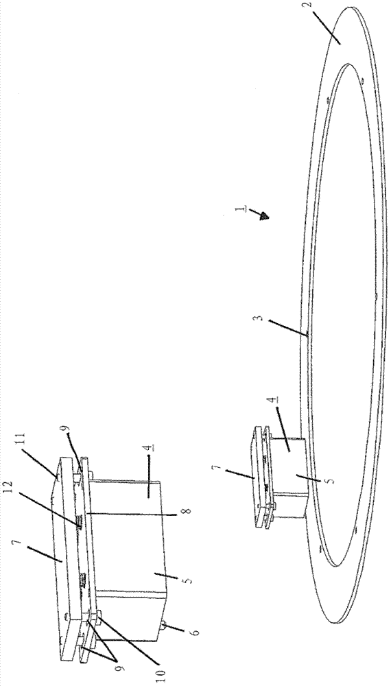
[0026] figure 1A first possible embodiment for a calibration body with a sensor device is shown in a perspective view. In this case, an annular element 2 is provided as calibration body 1 , which can be screwed, for example, on the end side by means of a bore 3 in the shaft. The shaft itself is not shown. The marking body provided on the ring element 2 is also not shown, wherein the marking body can be formed, for example, from one coding track or possibly also from up to three coding tracks. In this case, the individual coding tracks are arranged on different diameters, wherein at the same time it is ensured by the sensor device 4 that all coding tracks can be scanned by means of the sensor elements.

[0027] The sensor device 4 comprises a housing 5 which is held directly in radial contact with the ring element 2 by means of a pin 6 , while the housing 5 is additionally mounted axially floating. A mounting plate 7 is provided for this purpose, which can be fastened, for e...


PUM


Abstract

The invention relates to a sensor device 4 used together with a calibration body 1, especially a calibration body 1 used in a large-scale shaft. The sensor device comprises a sensor shell 5 with a valuation electronic device and at least one sensor element. In order to compensate a shaft radial and/or axial gap, the sensor shell 5 is suggested to be contacted with the calibration body 1 directly; wherein, the radial and/or axial positioning and tracking of the sensor shell 5 and/or the sensor element 35 are carried out via a guiding element and an applying element.

Description

technical field [0001] The invention relates to a sensor device for use with a calibration body, in particular a calibration body for large shafts, comprising a sensor housing with evaluation electronics and at least one sensor element. Background technique [0002] Such sensor devices are required, for example, when determining the absolute angular position of rotating parts such as shafts. For this purpose, sensor arrangements are also used to determine the rotational speed of the rotating part. For this purpose, calibration bodies are used which fulfill the function of sensor devices, for example in the optical or magnetic field. In addition to the absolute angular position, the rotational speed can also be determined alternatively by means of the sensor system and the reference body. In particular for rotating mechanical components such as shaft drives with highly dynamic control behavior, the state variables require rotor position and rotational speed. In this case, ...

Claims


Application Information

Patent Timeline
Patent Type & Authority Applications(China)
IPC IPC(8): G01B21/22G01P3/44
CPCG01D5/12G01P3/487G01D11/245G01P1/026
Inventor B.斯特里茨克H.霍勒
Owner LENORD BAUER & CO
Why Eureka
Try Eureka