Trailer towing device for a tractor vehicle

a technology for tractor vehicles and towing devices, which is applied in the direction of towing devices, vehicle components, transportation and packaging, etc., can solve the problems of premature wear of bearings, small structural space available for integrating rollers, and reduced service li

Inactive Publication Date: 2013-01-03
ZF FRIEDRICHSHAFEN AG
View PDF5 Cites 19 Cited by
  • Summary
  • Abstract
  • Description
  • Claims
  • Application Information

AI Technical Summary

Benefits of technology

[0022]The angle detection device is preferably arranged within the trailer towing device. In particular, the angle detection device is arranged within one or more structural elements or within one or more assemblies of the trailer towing device, for example within the ball joint or the ball support housing. In this way the angle detection device can be protected effectively against environmental influences such as dirt and water. Advantageously, no components of the angle detection device are provided on the trailer vehicle itself. In this way an overall more compact structure of the angle detection device can be produced. External disturbing influences on the angle detection device can also be kept small, so that the angle detection device can operate in a relatively robust manner.
[0025]Preferably, the angle detection device works magnetically. In particular, one of the components comprises or is a magnet and another of the components comprises a sensor sensitive to magnetic fields, through which the magnetic field of the magnet advantageously flows. In particular the magnet and the magnetic-field-sensitive sensor are orientated relative to one another in such manner that the magnetic-field-sensitive sensor can detect rotation of the coupling ball about the vertical axis, around the joint ball. Preferably, the magnet and the magnetic-field-sensitive sensor are so orientated relative to one another that the magnetic-field-sensitive sensor can detect rotation of the coupling ball around the joint ball, about the vertical axis or about a number of axes, one of which in particular is the vertical axis. Advantageously, the magnet and the magnetic-field-sensitive sensor are so orientated relative to one another that the magnetic-field-sensitive sensor can detect rotation of the coupling ball around the joint ball, about the vertical axis and about one, about at least one, for example two or three, about several, or about any number of other axes, which preferably do not coincide with the vertical axis and in particular which pass through the mid-point of the joint ball and / or through the mid-point of the coupling ball. For example, by means of the magnetic-field-sensitive sensor the orientation of the field lines of the magnetic field can be detected. Preferably the first component comprises or is the magnet and the second component preferably comprises or is the magnetic-field-sensitive sensor. In particular, the magnet is a permanent magnet. In this way there is no need to run electric leads to the magnet. The magnet can have a rod-like, cylindrical, square, disc, annular, spherical or any other suitable shape.
[0030]In a further development, the trailer towing device comprises a shaft that connects the coupling ball to the angle detection device. This makes it possible to position the angle detection device outside the hollow space and / or a distance away from the bearing surfaces of the ball joint. Preferably, the angle detection device is arranged in the area of or close to the end of the ball support remote from the joint ball. The shaft is in particular connected firmly, preferably solidly or in a rotationally fixed manner to the coupling ball. Advantageously, the shaft is fixed to the wall of the coupling ball that delimits the hollow space. Preferably, the shaft connects the coupling ball to the first component of the angle detection device. The shaft preferably extends in the direction of the vertical axis and in particular can be rotated about the vertical axis. Advantageously, the rotational axis of the shaft coincides with the vertical axis.
[0031]Tilting of the coupling ball, i.e. rotation of the coupling ball around the joint ball about an axis that does not coincide with the vertical axis and in particular which passes through the mid-point of the joint ball and / or the coupling ball, can have the result that the rotational axis of the shaft no longer coincides with the vertical axis. This brings the risk that the function of the angle detection device may be impaired and / or that the shaft is permanently deformed and / or kinked. Preferably therefore, the shaft is completely flexible or at least flexible in a flexible area, in particular one that is made flexible and / or elastic, and it can therefore also be referred to as a flexible shaft. In this way the shaft can bend in the area so as to follow the tilting of the coupling ball. In addition or alternatively the shaft is hinged in at least one area and can also be called a hinged shaft. Thus, by deflection of the area the shaft can follow the tilting of the coupling ball. For example the shaft is designed as a hinged shaft, in particular having one or more hinges, and / or is made in several articulated parts. When the coupling ball is not tilted, the shaft is preferably straight and extends in the direction of the vertical axis. When the shaft bends and / or is deflected, its length in particular in the direction of the vertical axis changes, and this can for example be allowed for in the mounting of the shaft. Preferably this change can be detected by the angle detection device or by means of an additional sensor. This makes it possible to determine the angle through which the coupling ball has tilted around the joint ball. The angle is also called the tilt angle. By virtue of the magnetically operating angle detection device tilting of the coupling ball can be detected since the distance between the magnet and the magnetic-field-sensitive sensor changes. If the shaft is a flexible shaft, then by means of it the coupling ball can preferably be moved back to a reference position after rotating and / or tilting.

Problems solved by technology

In particular, owing to the small diameter of the coupling head only little structural space is available for integrating the roller bearing, which as a rule comprises many moving parts, in the coupling head, which has to withstand large forces during trailer towing operation and can therefore only be made smaller to a limited extent at acceptable cost.
Furthermore, roller bearings are also sensitive to point loading that often occurs during trailer towing operation, so that such bearings undergo premature wear.

Method used


Image

  • Trailer towing device for a tractor vehicle
  • Trailer towing device for a tractor vehicle
  • Trailer towing device for a tractor vehicle

Examples


Embodiment Construction

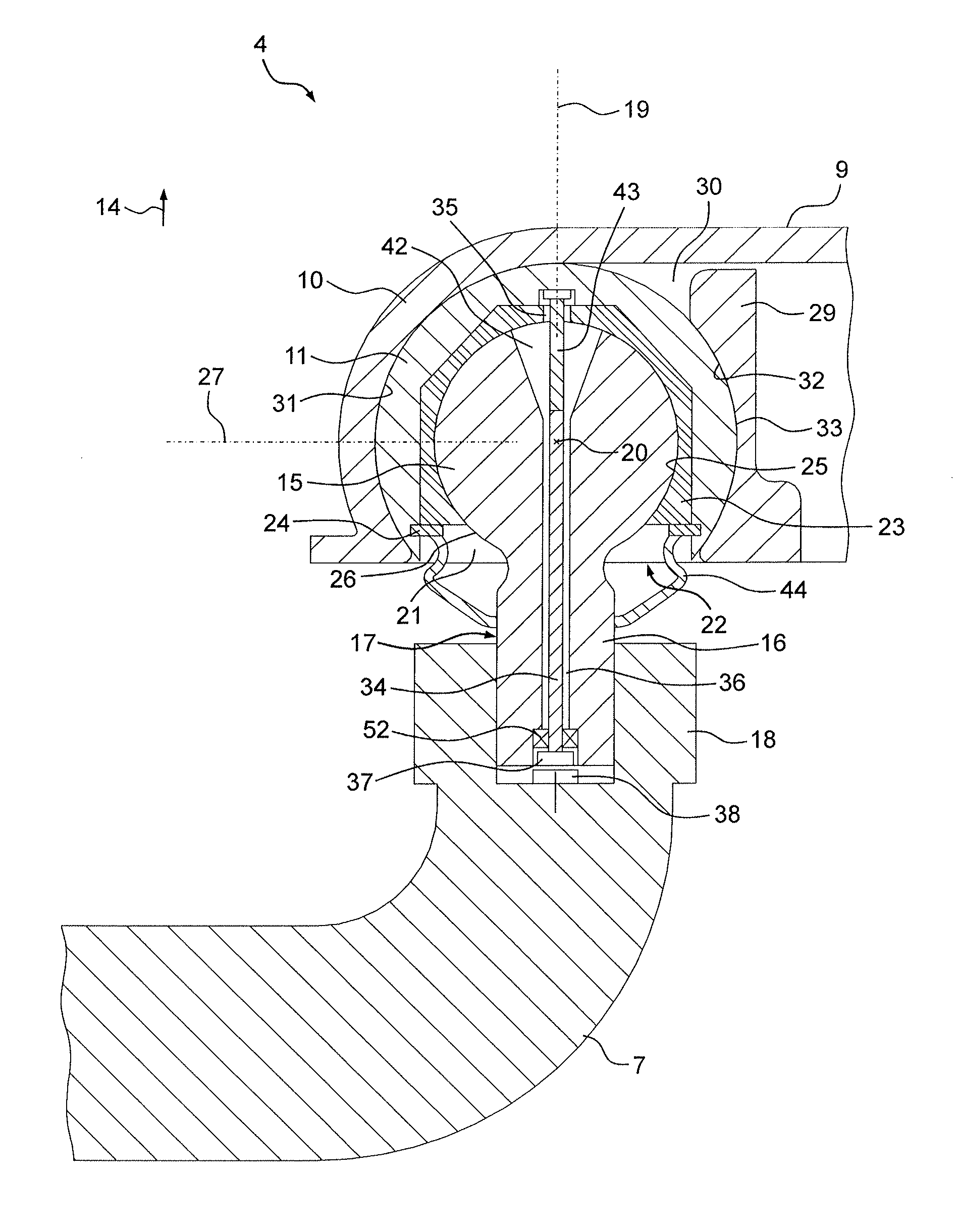
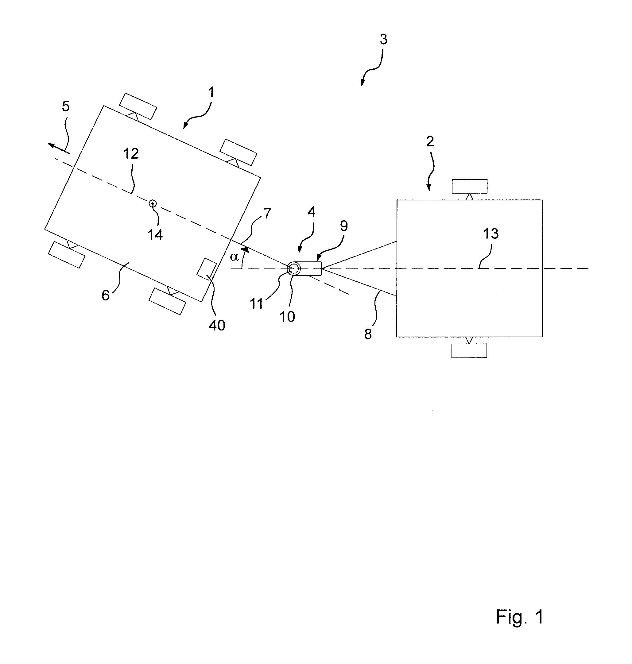
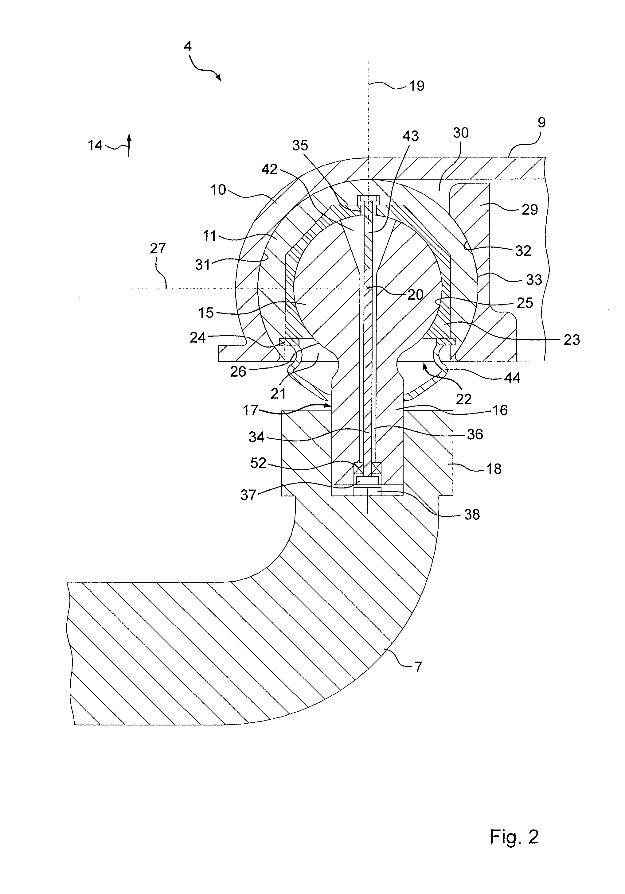
[0043]FIG. 1 shows a view from above, of a combination 3 consisting of a tractor vehicle 1 and a trailer vehicle 2, wherein the tractor vehicle 1 is articulated to the trailer vehicle 2 by means of a first embodiment of a trailer towing device 4. The usual forward-driving direction of the combination 3 is indexed 5. The trailer towing device 4 comprises a holder 7 in the form of a coupling arm which is solidly connected to the vehicle body or chassis 6 of the trailer vehicle. In addition a coupling lock 9 is fixed to a tow-bar 8 of the trailer vehicle 2, which comprises a ball seating 10 into which fits a schematically represented coupling ball 11 arranged at an end of the coupling arm 7 at the rear relative to the driving direction 5. The coupling lock 9 forms a front end of the tow-bar 8 in the driving direction 5.

[0044]The angle α between the longitudinal axis 12 of the tractor vehicle 1 and the longitudinal axis 13 of the trailer vehicle 2 forms the so-termed articulation or com...


PUM


Abstract

A trailer towing device for a tractor vehicle (1) which comprises a coupling ball (11), having a hollow space (21) for coupling a trailer vehicle (2), and a ball support (17) which engages with an end area in the hollow space (21) through an opening (22) provided in the coupling ball (11) and supports the coupling ball (11), such that the end area of the ball support (17) comprises a joint ball (15) on which the coupling ball (11) is fitted and can rotate so that, together with the coupling ball (11), the joint ball forms a ball joint (28).

Description

[0001]This application claims priority from German patent application serial no. 10 2011 078 329.6 filed Jun. 29, 2011.FIELD OF THE INVENTION[0002]The invention concerns a trailer towing device for a tractor vehicle, with a coupling ball having a hollow space for coupling a trailer vehicle and a ball support, which engages in the hollow space with one end area through an opening provided in the coupling ball and which supports the coupling ball.BACKGROUND OF THE INVENTION[0003]DE 103 34 000 A1 describes a trailer coupling for a tractor vehicle, with a coupling head for attaching a coupling counterpart of a trailer vehicle, a coupling shaft which is connected to the tractor vehicle and which, in the area of the coupling head, defines a vertical axis, and an angle sensor which is integrated in the trailer coupling and which registers movement of the coupling counterpart relative to the coupling shaft about the vertical axis. The coupling head is mounted so that by virtue of a roller b...

Claims


Application Information

Patent Timeline
Patent Type & Authority Applications(United States)
IPC IPC(8): B60D1/06
CPCB60D1/065B60D1/06B60D1/62B60D1/30
Inventor ADAMCZYK, DIRKSTRATMANN, JULIANELBERS, CHRISTOPH
Owner ZF FRIEDRICHSHAFEN AG
Why Eureka
Try Eureka