Device for dynamic balancing of a rotating component

a technology of rotating components and dynamic balancing, which is applied in the direction of dynamo-electric machines, centrifuges, structural associations, etc., can solve the problems of axial direction stabilization, and achieve the effects of increasing limit speed, constant air gap, and easy application

Inactive Publication Date: 2013-01-03
HANNING ELECTRO WERKE GMBH & CO KG
View PDF4 Cites 7 Cited by
  • Summary
  • Abstract
  • Description
  • Claims
  • Application Information

AI Technical Summary

Benefits of technology

[0008]The particular advantage of the invention resides in that a stabilizer unit for compensation of disturbing forces acting on a rotating component can be arranged outside an electric motor. The invention provides for spatial separation of a torque generated by the electric motor and a radial balancing force generated by the stabilizer unit. The electric motor can be provided with a constant air gap as customary between a stator and a rotor. Due to the fact that the stator is radially movable it is possible to apply the balancing force to the stator and from said latter to the shaft via bearing means. The root idea of this invention is to have a radial balancing force exerted on a non-rotating part of the electric motor, i.e. on the stator and / or on a bearing.
[0009]A preferred embodiment of this invention provides for the stator to be rigidly attached to a carrier housing that is movable by flexible bearing means in a radial direction at least. This affords the advantage that radial balancing forces can be easily applied to the stator and / or to the electric motor.
[0010]According to another preferred embodiment of the invention the stator is coupled to the outside of the stabilizer unit via a bearing of elastomeric material in a radial direction. External attenuation can be advantageously increased this way such that the limit speed may be increased under the aspect of ensuring a stable running performance of the rotating component.
[0011]A modification of this invention provides for a permanent-magnetic bias means to be arranged between the stabilizer unit and the stator to thereby improve the introduction of balancing forces.
[0012]According to another modification of the invention the carrier housing supporting the electric motor is attached to an enclosure of the centrifugal via an additional adapter casing in which case the stabilizer unit is disposed inside said carrier housing. This affords the advantage that centrifugals affected by unbalance can be retrofitted with unbalance compensating drives since all it takes here is to rigidly attach the carrier housing to the enclosure of the centrifugal via fixing means.
[0013]Other advantages of this invention are as disclosed in the further subclaims.

Problems solved by technology

The drawback affecting this prior known device is that stabilization can be achieved in an axial direction only.

Method used


Image

  • Device for dynamic balancing of a rotating component
  • Device for dynamic balancing of a rotating component

Examples


Embodiment Construction

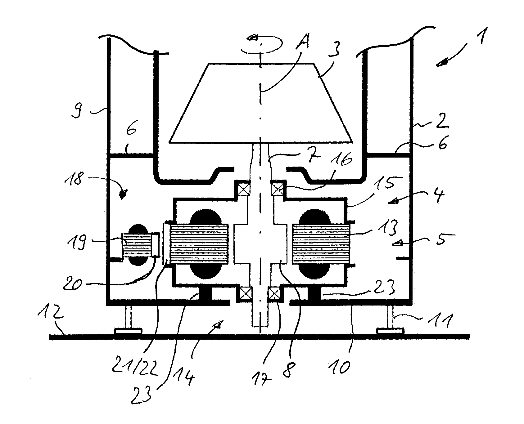
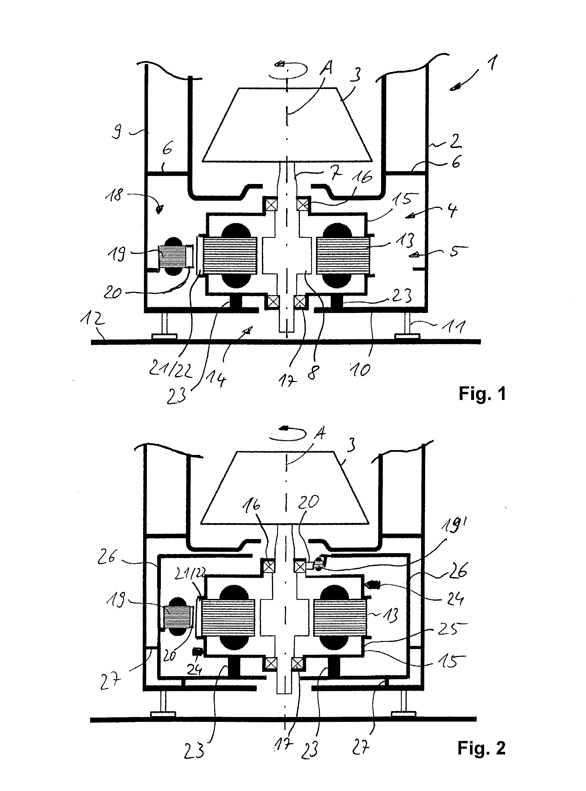
[0018]A device according to this present invention for limiting unbalance can be used in centrifugals, textile machines, domestic appliance or other types of stirrers. Following is a description with reference to the figures of a centrifugal 1 with unbalance limiting devices of different design in the bottom area of the machine.

[0019]A centrifugal 1 normally comprises an enclosure 2 in which a rotating component 3 (rotor) is rotated around a vertical axis A by means of a drive unit 4 (electric motor). The enclosure 2 of the centrifugal 1 has a cylindrical side wall 9 and a bottom member 10 and is posted on a horizontal base 12 by means of feet 11 protruding from said bottom member in a spaced relation thereto. The drive unit 4 is disposed in a bottom chamber area 5 of the enclosure 2 which is separated from an upper area of the centrifugal 1 by partitions 6. A non-rotatable connection between the rotating component 3 and a shaft 7 is established via a central bore only. The shaft 7 ...


PUM


Abstract

A device for limiting an unbalance in inside a centrifugal, with an electric motor to drive a rotating component disposed in an enclosure around a rotational axis, wherein a rotor of the electric motor is non-rotatably connected to the rotating component, a bearing assembly for the rotor and the stator to be arranged in, and a stabilizer unit which generates as a function of a disturbing force acting on the rotating component a balancing force that is adapted to compensate said latter, the bearing assembly including support means such as to make the stator radially movable, and the stabilizer arranged radially outside and/or inside said stator and/or support means of the bearing assembly and having stabilizing means whereby in aggregate a radial balancing force can be generated.

Description

BACKGROUND OF THE INVENTION[0001]1. Field of the Invention[0002]This present invention relates to a device for dynamic balancing of a rotating component, in particular for limiting unbalance conditions inside a centrifugal, which comprises an electric motor to drive a rotating component disposed in an enclosure around a rotational axis wherein a rotor of the electric motor is non-rotatably connected to the rotating component, a bearing assembly for the rotor and stator to be arranged in, and a stabilizer unit which generates as a function of a disturbing force acting on said rotating component a balancing force that is adapted to compensate said latter.[0003]2. Description of the Related Art[0004]Prior known from DE 198 02 950 A1 is a device for limiting unbalance in a centrifugal which has a rotating component that is rotatably mounted in a frame. This rotating component is driven by an electric motor disposed on a first end of a shaft that is non-rotatably connected to the rotatin...

Claims


Application Information

Patent Timeline
Patent Type & Authority Applications(United States)
IPC IPC(8): H02K5/24
CPCB04B9/12B04B9/146H02K5/26H02K7/04H02K7/09H02K2213/09H02K7/16H02K11/00
Inventor STALLINGER, THOMASAMRHEIM, WOLFGANGSILBER, SIEGFRIEDGRABNER, HERBERT
Owner HANNING ELECTRO WERKE GMBH & CO KG
Why Eureka
Try Eureka