
Optical system of an endoscope, endoscope, stereo-video endoscope, and method for producing an optical system

a technology of optical system and endoscope, which is applied in the field of optical system, can solve the problems of difficult positioning of the mask correctly during assembly, complicated production process, and difficulty in producing a very thin mask, and achieve the effect of simplifying the configuration

Pending Publication Date: 2020-11-19
OLYMPUS WINTER & IBE
View PDF3 Cites 1 Cited by
  • Summary
  • Abstract
  • Description
  • Claims
  • Application Information

AI Technical Summary

Benefits of technology

The patent text describes a method for producing an optical system with a simplified design and easier production. By eliminating the need for a fragile and thin mask, the production process is faster and more reliable. The coating can be applied using various methods such as vapor deposition or sputter deposition, and the desired function of the coating can be achieved even if it is not applied precisely at the desired position. The optical system can also be further improved by providing the coating exclusively on the first or second outlet side of the prisms, which can reduce the complexity of the system. Overall, this method simplifies the production and assembly of the optical system and improves its functionality.

Problems solved by technology

Producing a very thin mask is, however, a technically elaborate process.
Assembling the optical system is also a technical challenge since such a thin mask can only be handled with the utmost care and requires a great deal of experience.
It is difficult to position the mask correctly during assembly and, above all, not to damage it.
The size of the air gap lies in a range which cannot be achieved when an aperture is used.
In addition, metal is ductile, so that it is unlikely that the coating will chip.
The handling of such a mask is very demanding and is not successful in all cases.
This leads to delays in production and unnecessary rejects.

Method used


Image

  • Optical system of an endoscope, endoscope, stereo-video endoscope, and method for producing an optical system
  • Optical system of an endoscope, endoscope, stereo-video endoscope, and method for producing an optical system
  • Optical system of an endoscope, endoscope, stereo-video endoscope, and method for producing an optical system

Examples


Embodiment Construction

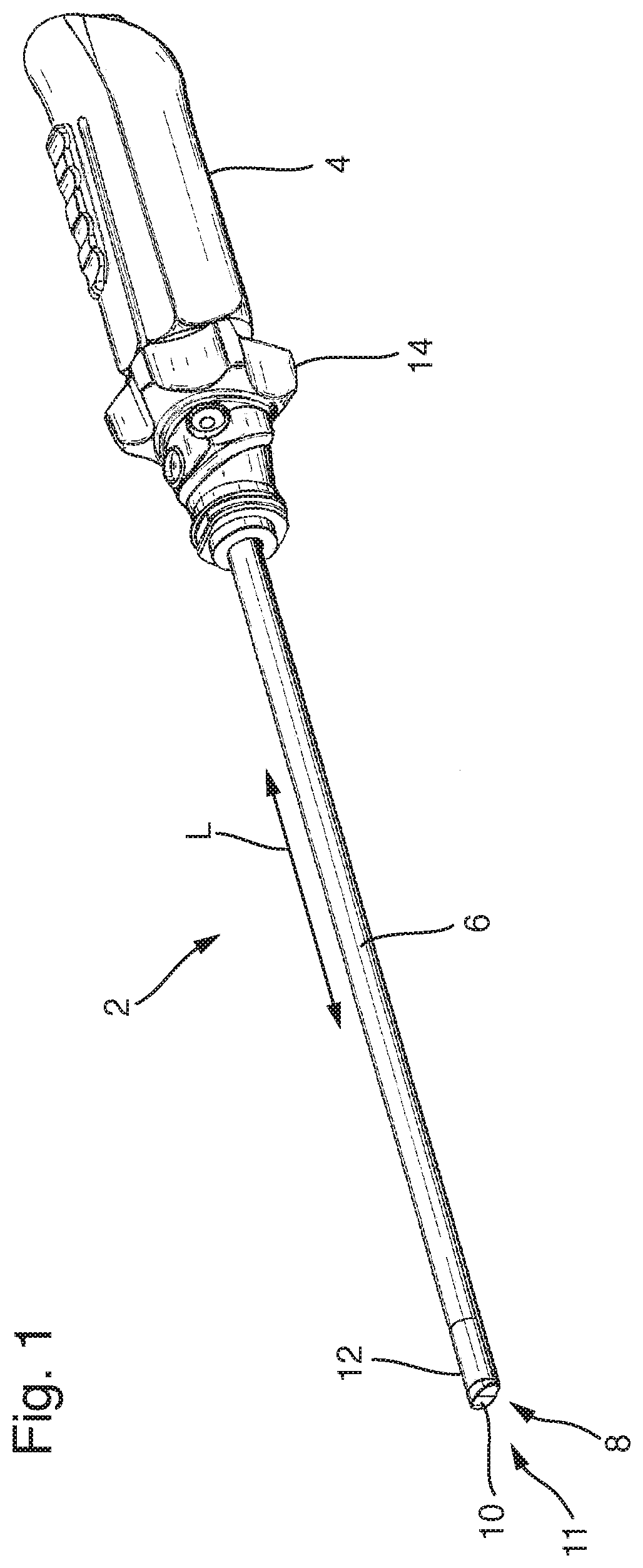
[0040]FIG. 1 shows a schematically simplified perspective representation of an endoscope 2, comprising a proximal handle 4, to which a rigid endoscope shaft 6, merely by way of example, is joined. The endoscope shaft 6 can likewise have a flexible or semi-flexible configuration. At the distal tip 8 of the endoscope shaft 6 there is situated an inlet window 10, through which light from an object space 11, for example an operating or observation field, enters an optical system of the endoscope 2 which is not visible in FIG. 1. The optical system is, for example, arranged in a distal portion 12 of the endoscope shaft 6. The optical system images objects, which are situated in the object space 11, on at least one image sensor. For this purpose, the optical system comprises at least one image sensor. The image sensor(s) can be one(s) having a high resolution, e.g. HD, 4K or following technologies.

[0041]The endoscope 2 is, for example, a surgical instrument. It is an endoscope 2 having a ...


PUM


Abstract

An optical system of an endoscope having a lateral viewing direction, the optical system including: a sideways looking distal optical assembly; and a proximal optical assembly, wherein light bundles incident from an object space are guided along a beam path by the distal and proximal optical assemblies and imaged on an image sensor; the distal optical assembly comprises a deflection prism assembly having first and second prisms arranged in a direction of incident light; the first prism has first inlet and inclined first outlet sides; the second prism has second inlet, reflection, and second outlet sides; and the first outlet side of the first prism and / or the second inlet side of the second prism have a coating in a region outside of the beam path to form an air gap in a region of the beam path between the first outlet and second inlet sides.

Description

CROSS-REFERENCE TO RELATED APPLICATION[0001]The present application is a continuation of PCT / EP2019 / 052515 filed on Feb. 1, 2019, which is based upon and claims the benefit to DE 10 2018 102 641.2 filed on Feb. 6, 2019, the entire contents of each of which are incorporated herein by reference.BACKGROUNDField[0002]The present disclosure relates to an optical system of an endoscope having a lateral viewing direction, comprising a sideways looking distal optical assembly and a proximal optical assembly, wherein light bundles incident from an object space are guided along a beam path by the optical assemblies and imaged on an image sensor, wherein the distal optical assembly comprises a deflection prism assembly which comprises a first prism and a second prism which follow one another in the direction of incident light, wherein the first prism comprises a first inlet side and a first outlet side inclined with respect thereto, and wherein the second prism comprises a second inlet side, a...

Claims


Application Information

Patent Timeline
IPC IPC(8): G02B23/24G02B1/10G02B17/04
CPCA61B1/00193G02B23/2415A61B1/0011A61B1/00177G02B23/243A61B1/04G02B17/04A61B1/00096G02B1/10G02B5/04G02B23/2423
Inventor ZHAO, JIANXIN
Owner OLYMPUS WINTER & IBE
Learn More