
Axial flux machine and method for the manufacturing thereof

a technology of axial flux machine and axial flux, which is applied in the direction of machines/engines, manufacturing stator/rotor bodies, mechanical apparatus, etc., can solve the problems of complex and/or heavier (attachment to the) wind turbine base, difficult use of such facilities, and inability to adjust, etc., to achieve the effect of narrowing the air gap, improving reliability and improving reliability

Inactive Publication Date: 2022-03-17
JOVAL
View PDF3 Cites 0 Cited by
  • Summary
  • Abstract
  • Description
  • Claims
  • Application Information

AI Technical Summary

Benefits of technology

The patent describes a method for manufacturing an axial flux machine and a wind turbine with a fixed stator and blades. The method involves placing various stator parts on flat support surfaces on a table that are perpendicular to the axis of rotation. This allows for precise control over how the stator parts will orient themselves relative to the axis of rotation. A narrow air gap is achieved between the stator and rotor, which increases the efficiency of the generator. The use of a fixed shaft and even distribution of fixing points also contribute to a lightweight and cost-effective assembly.

Problems solved by technology

However, when scaling up an axial flux machine to such Megawatt applications, manufacturers are faced with a number of problems.
This entails large costs and certain conditions, such as much wind, will make the use of such facilities more difficult.
A large weight of the generator also makes the (attachment to the) wind turbine base more complex and / or heavier.
As a consequence, how to make the stator(s) and rotor(s) as lightweight as possible despite their large dimensions, proves to be a problem.
In addition, the full weight of the assembly to be mounted, which is also determined by the weight of for instance vanes and a turbine housing, needs to be limited as much as possible.
During the operation of a wind turbine generator, enormous mechanical forces also occur as a result of the high capacities and large peripheral velocities.
As a consequence, manufacturers are faced with the problem of how the various stator parts and rotor parts can be sufficiently firmly anchored so as to obtain a robust and durable machine.
The costs of manufacturing the generator constitute an important part thereof.
As a consequence, manufacturers are faced with the problem of how the generator can efficiently be made despite the above demands made on the design.
This makes the assembling more difficult and there is a risk of damaging the (insulating) exterior surface of the stator teeth.
The production of the annular circumference, of which the cooling fins preferably form an integral part, is not easy to execute either.
Particularly when it regards a large circumference, an expensive production technique is required.
To conclude with, the method and the design of WO2018 / 015293 do not in any way guarantee the accurate thickness of the narrow air gap, which may cause problems with stators and rotors of large dimensions.
The specific configuration, however, renders the production of these parts difficult, and positioning requires extra parts, such as plates or a ring having apertures attaching the stator teeth to each other.
Moreover, no internal cooling fins between the stator teeth are provided in this solution.
This facilitates the assembling but results in a less efficient cooling.
However, there still is a turbine housing causing extra weight, and no solution is described for limiting the weight of rotor and stator.

Method used


Image

  • Axial flux machine and method for the manufacturing thereof
  • Axial flux machine and method for the manufacturing thereof
  • Axial flux machine and method for the manufacturing thereof

Examples


Embodiment Construction

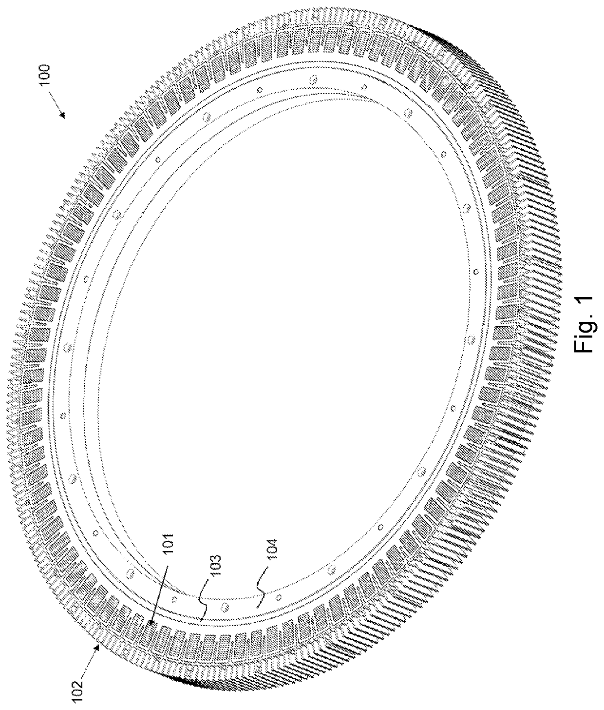
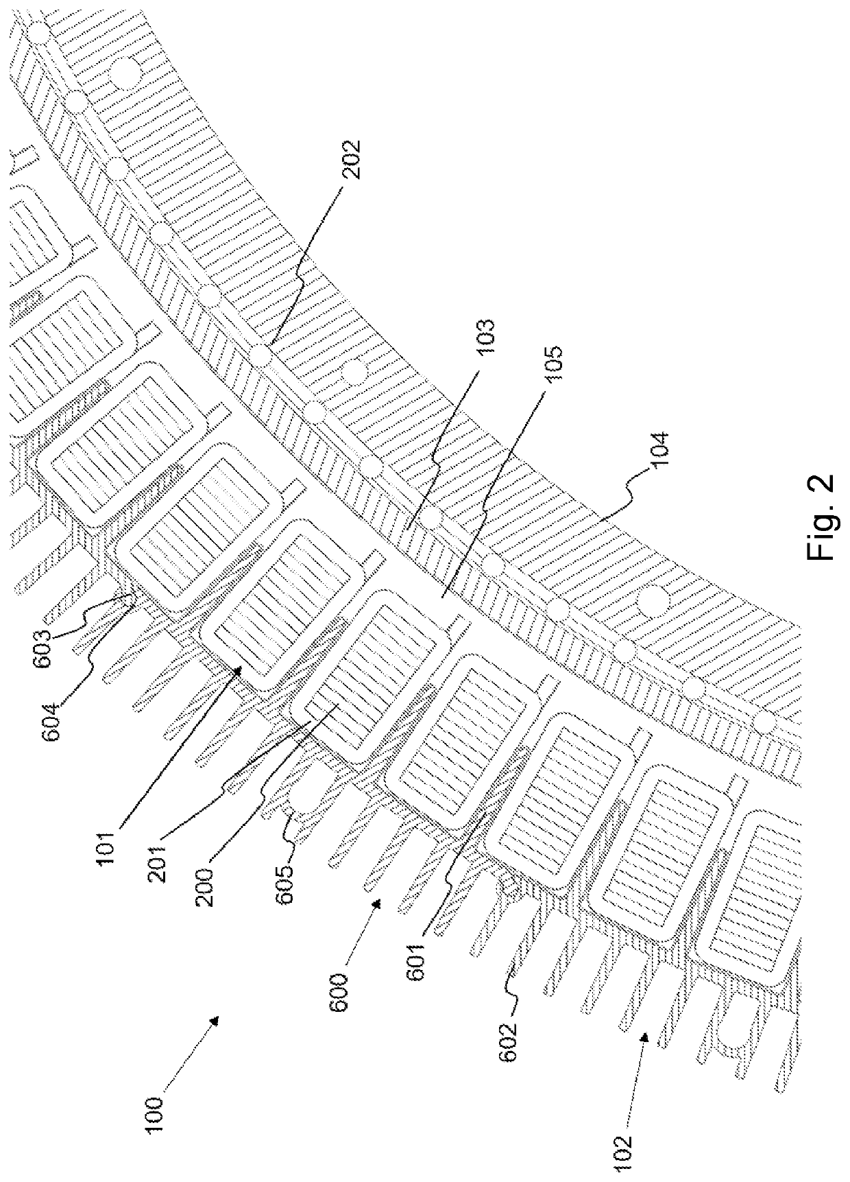
[0074]FIG. 1 shows a 3D-reproduction of a stator (100) after manufacturing according to an embodiment of the invention. FIG. 2 shows a cross-section perpendicular to the axis of rotation of this stator (100). In the embodiment shown, the stator (100) is a disk of a specific thickness, measured along the axis of rotation, in the center of which there is an aperture intended for the shaft of the machine.

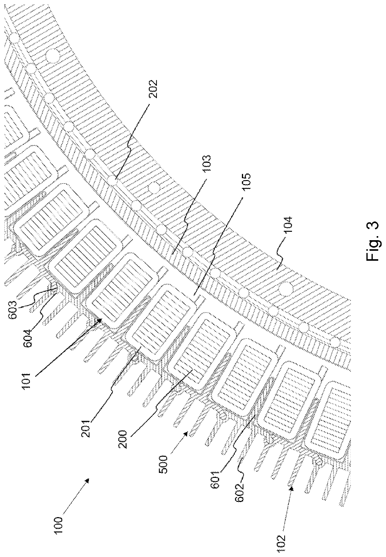
[0075]FIG. 1 and FIG. 2 show a stator ring (100) wherein the inner circumference is formed by a ring element (103) and the outer circumference is formed by boundary elements (102). The stator ring (100) forms an integral unit, bounded by the ring element (103) and the boundary elements (102), the stator elements being anchored in a filling material (105). In the embodiment of FIG. 1 and FIG. 2, the ring element (103) is the outer ring of a radial bearing. The ring element (103) could also be referred to as a race element (103) or outer race (103). The radial bearing may be of any suita...


PUM


Abstract

A method for manufacturing an axial flux machine adapted for generating a magnetic flux along the axis of rotation, includes the manufacturing of one or more stators, having the following steps: providing a surface comprising one or more flat support surfaces perpendicular to the axis of rotation; positioning one or more boundary elements, individual stator elements, and a ring element on the one or more support surfaces. At least one of the boundary elements is a cooling element adapted for conducting heat. The stator elements each has a ferromagnetic core and an electric winding wound around the ferromagnetic core, and filling the empty space between the outer circumference, the stator elements and the ring element with an electrically insulating filling material.

Description

TECHNICAL DOMAIN[0001]The present invention generally relates to an axial flux machine and a method for its manufacturing. The invention in particular provides a method enabling the manufacturing of a high-yield machine that is lightweight yet robust, and which can be made in an efficient manner.BACKGROUND OF THE INVENTION[0002]Within the range of electrical machines, for instance generators and motors, axial flux machines are a type with promising characteristics. Axial flux machines use a fundamentally different configuration than the more classic radial flux machines. Whereas in a radial flux machine the flux is generated in radial direction, in an axial flux machine this takes place in axial direction, that means along the direction of the axis of rotation. Typically, use is then made of permanent magnets that are arranged on two parallel rotor disks. The permanent magnets have been magnetized in axial direction, and the rotor disks are perpendicular to the axis of rotation. A s...

Claims


Application Information

Patent Timeline
IPC IPC(8): H02K15/00H02K5/173H02K7/08H02K7/18H02K21/24F03D80/70
CPCH02K15/00H02K5/1737H02K7/086H02K7/183F05B2240/10F03D80/70F05B2240/60F05B2240/50H02K21/24H02K1/182H02K7/1838H02K15/02Y02E10/72H02K9/227H02K9/223
Inventor VERSAVEL, JOZEF ROBRECHT JAN
Owner JOVAL
Learn More