
Light Collector With Complementing Rotationally Asymmetric Central And Peripheral Lenses

a technology of central and peripheral lenses and light collectors, which is applied in the field of illumination devices, can solve the problems of inability to meet the requirements of efficient light emitting area, led projecting systems that have not yet been able to meet the requirements of light application systems, and the presently unsuccessful use of leds in connection with light application systems

Active Publication Date: 2013-01-03
MARTIN PROFESSIONAL
View PDF10 Cites 22 Cited by
  • Summary
  • Abstract
  • Description
  • Claims
  • Application Information

AI Technical Summary

Benefits of technology

This approach increases the efficiency of light collection and distribution, improving the uniformity and quality of illumination while minimizing color artifacts, allowing for higher lumen output within limited space and maintaining power efficiency.

Problems solved by technology

However, LEDs have not presently been successfully used in connection with light application systems where an image is created and projected towards a target surface.
LED projecting systems have not yet been able to fulfill these requirements.
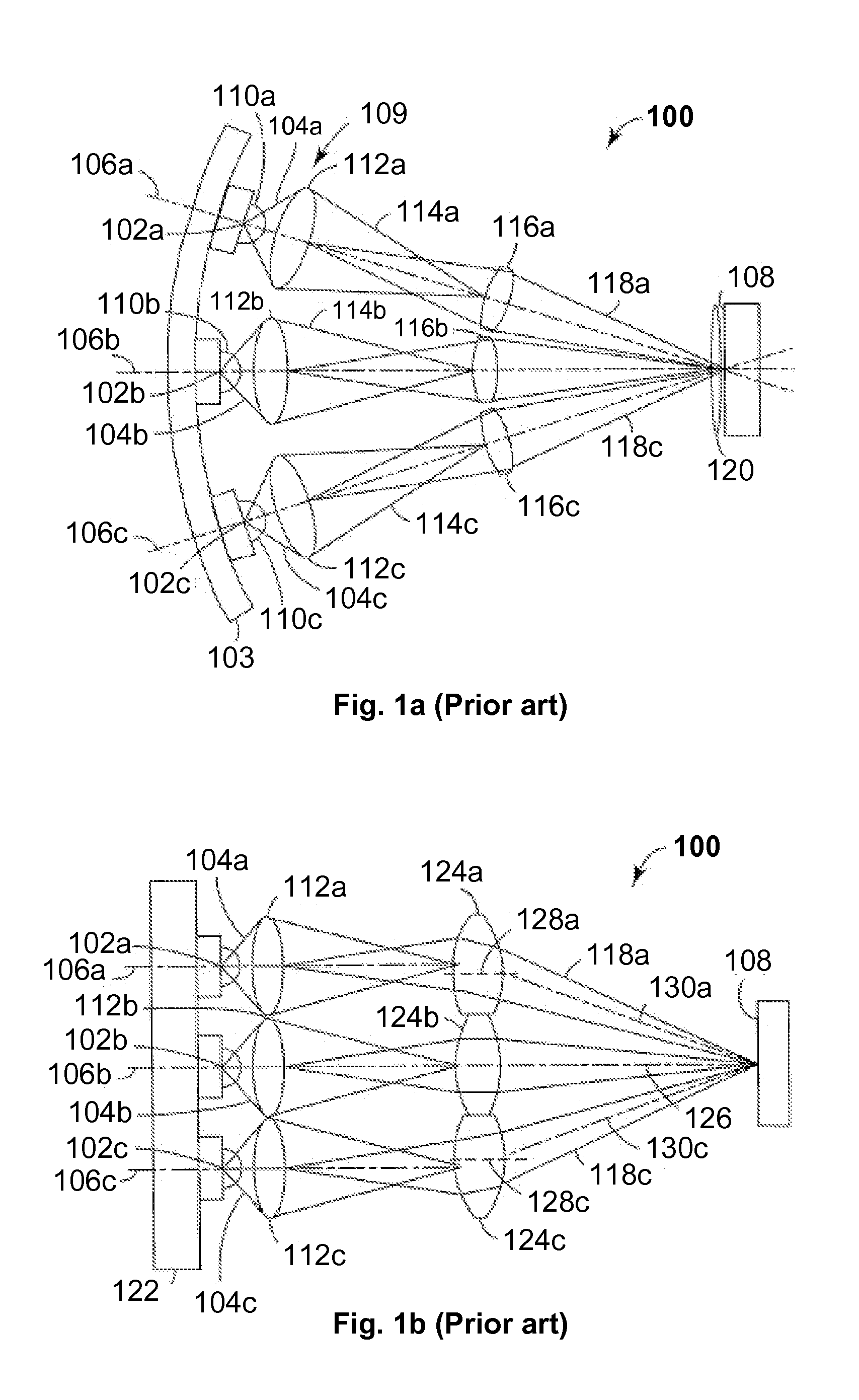
The LED is encapsulated into the tube which optically reduces the efficient light emitting area of the LED and it is as a consequence difficult to maintain etendue through the entire optical system.
Further it is difficult to design the focusing properties of the tube as focusing is performed by the hybrid exiting surface which constraints the designin options as only two surfaces parts can be adjusted.
Yet another issue is the fact the high power LED used today often need cooling which is difficult provide when the LED is encapsulated into the tube.
The consequence is, however, that the efficiency with regard to power consumption versus light output is very low.
Furthermore, a large amount of light is lost as the prior art fixtures typically only couple a central part of the light of the light beams through the gate in order to provide a uniform illumination of the gate, which again reduces the efficiency.
The space in light fixtures is often limited and it is difficult to fit many light sources into prior art fixtures, for instance because the optical components associated with the light sources often take up a lot of space.
Yet another aspect is the fact that color artifacts often appear in the output from fixtures having light sources of different colors.
The reason for this is the fact that high performance LEDs used for stage-illumination have large, rectangular die areas of 5-12 mm2 and even higher This implies, that it is notr possible to model the primary optics to a point source since the size-ratio between the primary optics and the LED die can get rather small.
Compared to discharge lamps, these patches are ill fitted to smoothly fill out the circular spot profiles of stage-illumination instruments.

Method used


Image

  • Light Collector With Complementing Rotationally Asymmetric Central And Peripheral Lenses
  • Light Collector With Complementing Rotationally Asymmetric Central And Peripheral Lenses
  • Light Collector With Complementing Rotationally Asymmetric Central And Peripheral Lenses

Examples


example

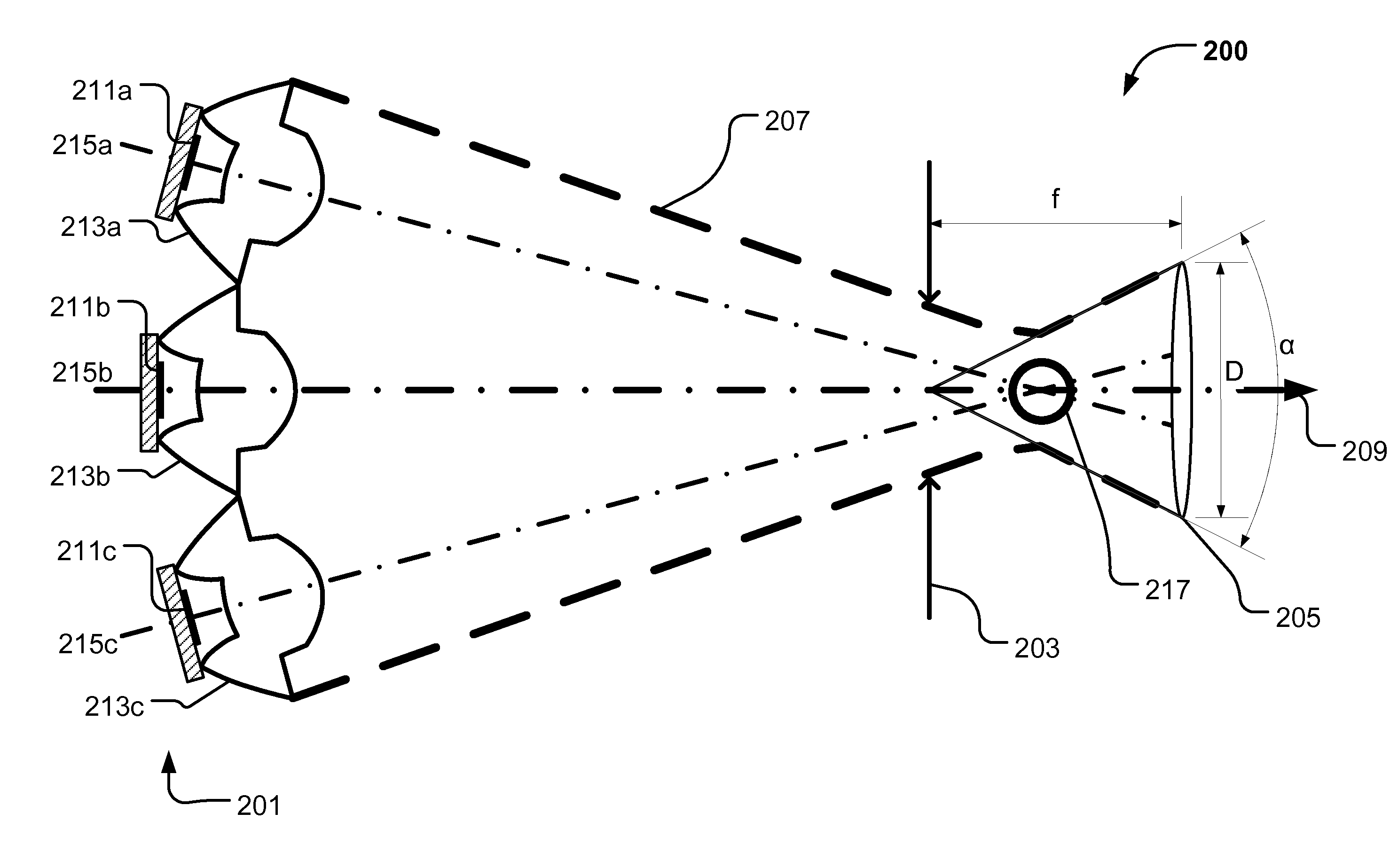
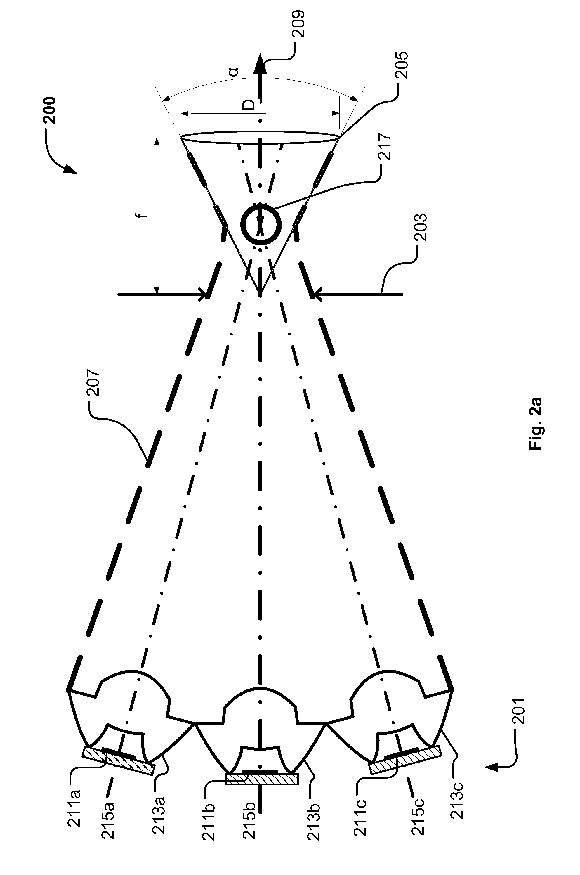
[0090]The color mixing of the illumination device of FIGS. 5a and 5b was be improved by using the light collector as illustrated in FIG. 10a-10f. In the following the light collector is referred to as a NRS TIR-lens (Non-rotational-symmetric TIR lens) The TIR lenses were thus modified to project a rounder spot and provide better color-mixing. However it was deemed impractical to simulate the entire illumination device of FIGS. 5a and 5b with 7 LEDs, 7 TIR-lenses and secondary optics, a process that would take up to several minutes per optimization step. Instead, a single NRS TIR-lens was optimized by data from a 25 mm {circle around ( )} gate, reducing each step to ≈6-9 seconds.

[0091]The NRS TIR-lens design was found by first optimizing a rotationally symmetric TIR-lens as illustrated in FIG. 8a for maximum luminous output in the optical gate of the illumination device of FIGS. 5a and 5b. However the skilled person realizes that any basic rotationally symmetric TIR-lens design known...


PUM

PropertyMeasurementUnit
areasaaaaaaaaaa
angleaaaaaaaaaa
heightaaaaaaaaaa

Abstract

The present invention relates to a light collector for collecting light emitted by a light source and converting the collected light into a light beam. The light collector comprises a central lens part aligned along an optical axis of the light source where the central lens comprises a central entrance surface and a central exit surface. The light collector also has a peripheral lens part surrounding at least of part of the central lens. The peripheral lens comprises a that said central lens and said peripheral lens is mutual adapted to convert said light emitted by said light source into a common light beam having a substantial circular and rotationally symmetric cross sectional light distribution, where said common light beam comprises said first light beam part and said second light beam part.

Description

FIELD OF THE INVENTION[0001]The present invention relates to an illumination device illuminating an optical gate and projecting an image of the optical gate towards a target surface. The illumination device comprises a light source module generating light, an aperture delimiting the optical gate and a projecting system adapted to project the optical gate at a target surface.[0002]The present invention also relates to a light collector for collecting light emitted by a light source and converting the collected light into a light beam. The light collector comprises a central lens part aligned along an optical axis of the light source where the central lens comprises a central entrance surface and a central exit surface. The light collector also has a peripheral lens part surrounding at least part of the central lens. The peripheral lens comprises a peripheral entrance surface, a peripheral reflection surface and a peripheral exit surface.BACKGROUND OF THE INVENTION[0003]Light emitting...

Claims


Application Information

Patent Timeline
Patent Type & Authority Applications(United States)
IPC IPC(8): F21V13/04F21V7/00F21V5/04
CPCF21S10/007F21V5/008F21V5/04F21V7/0091F21W2131/406F21Y2101/02Y10T29/49764G02B27/0905G02B27/0955G02B19/0066G02B19/0028G02B19/0061G02B26/007F21Y2115/10
Inventor JENSEN, THOGERGADEGAARD, JESPERJORGENSEN, DENNIS
Owner MARTIN PROFESSIONAL
Learn More