Context-Based Target Recognition

a target recognition and context-based technology, applied in the field of processing images, can solve the problem that the false identification of objects may occur more often than desired

Active Publication Date: 2013-01-03
THE BOEING CO
View PDF5 Cites 45 Cited by
  • Summary
  • Abstract
  • Description
  • Claims
  • Application Information

AI Technical Summary

Problems solved by technology

With currently-available systems for target recognition using the number of images generated using synthetic aperture radar imaging, false identifications of objects may occur more often than desired.
Further, the time needed to recognize objects may be important when using that information to control the mobile platform or perform other actions that are time sensitive.

Method used


Image

  • Context-Based Target Recognition
  • Context-Based Target Recognition
  • Context-Based Target Recognition

Examples


Embodiment Construction

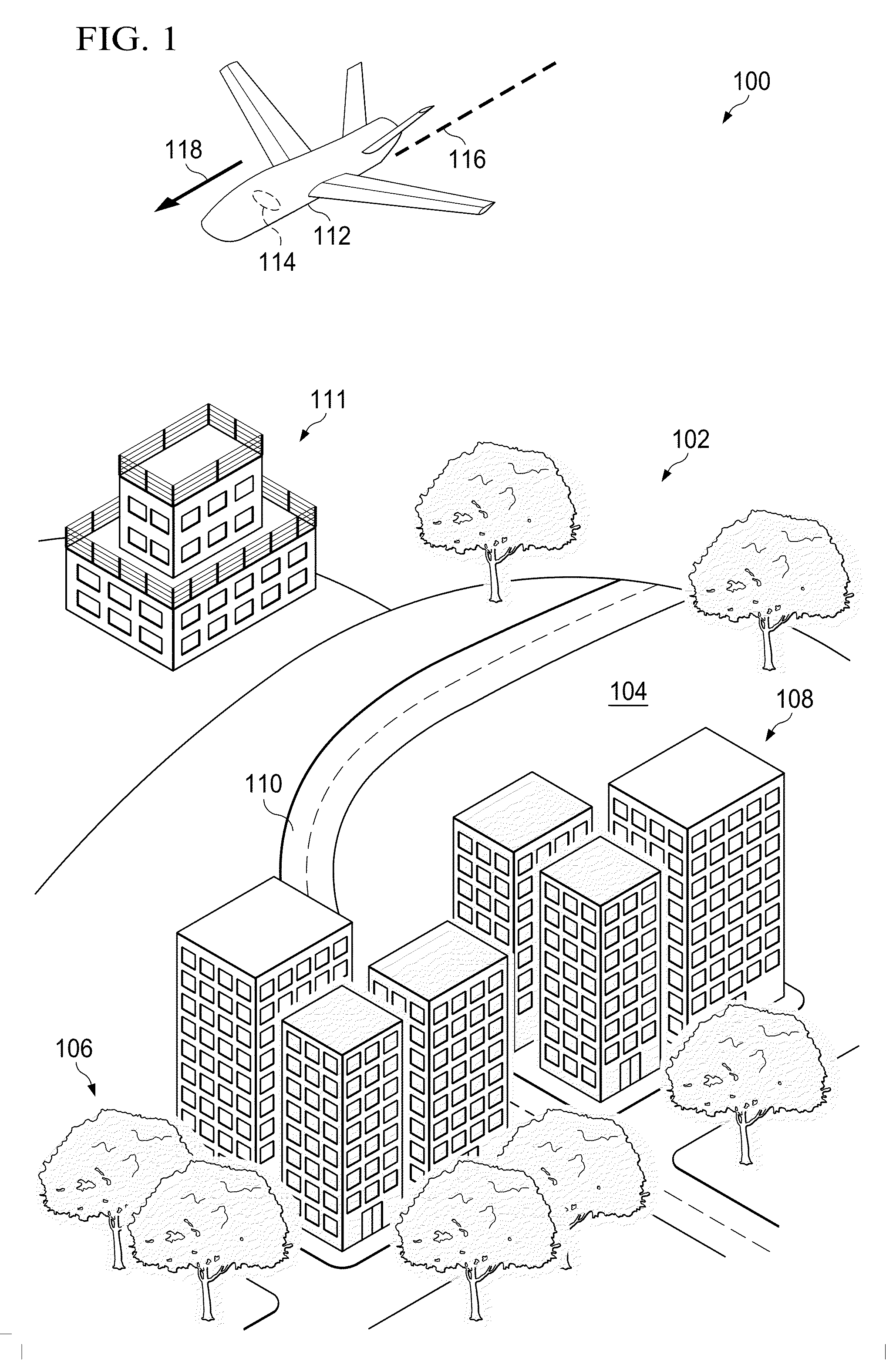
[0044]Referring now to the figures, in FIG. 1, an illustration of an imaging environment is depicted in accordance with an advantageous embodiment. In this illustrative example, imaging environment 100 is an environment in which images may be generated for area 102. Area 102 includes terrain 104, vegetation 106, buildings 108, road 110, ground station 111, and other objects within area 102.

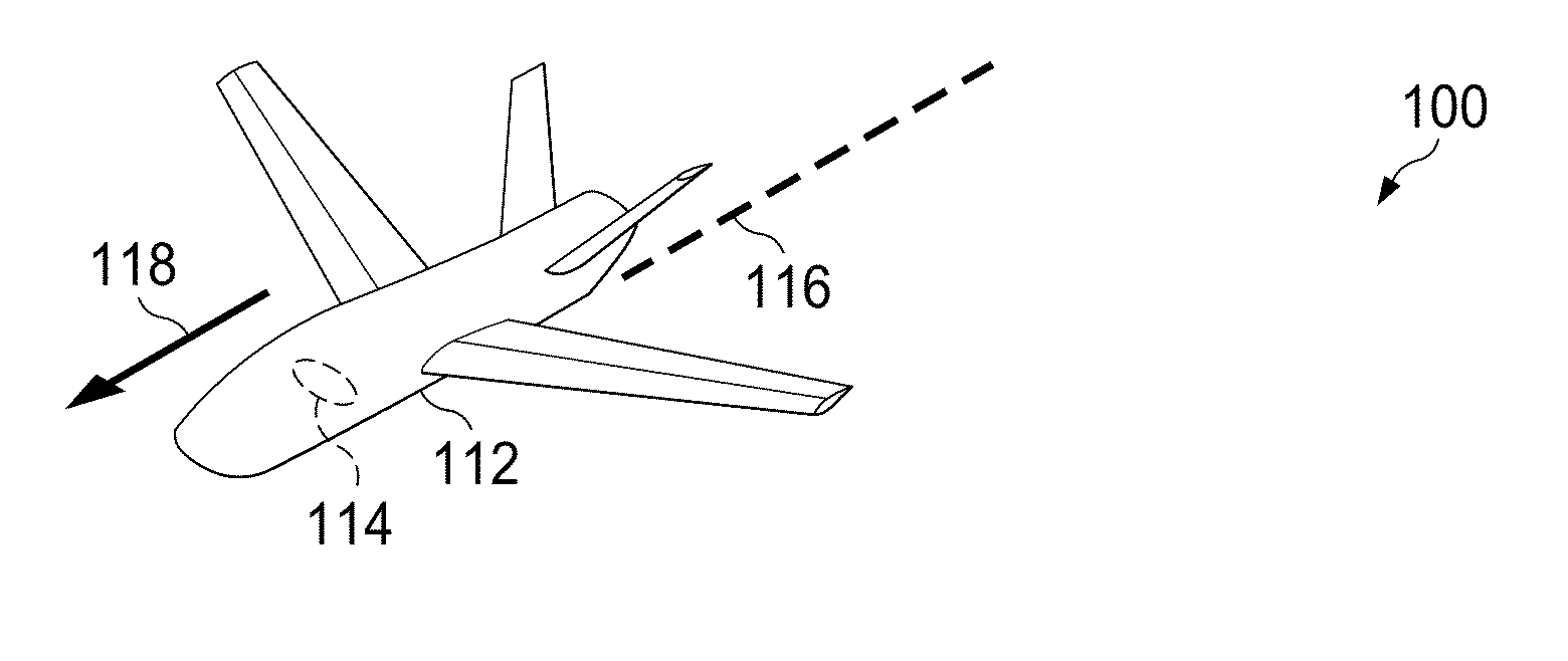
[0045]As depicted, unmanned aerial vehicle (UAV) 112 is present in imaging environment 100. Radar imaging system 114 is mounted to unmanned aerial vehicle 112. Radar imaging system 114 is a synthetic aperture radar (SAR) imaging system in this illustrative example.

[0046]Radar imaging system 114 is configured to send pulses of electromagnetic signals towards area 102 as unmanned aerial vehicle 112 moves along flight path 116 in the direction of arrow 118. Further, radar imaging system 114 is configured to detect electromagnetic signals reflected off of the various surfaces in area 102. These surfac...


PUM


Abstract

A method and apparatus for identifying a target object. A group of objects is identified in an image. The group of objects provides a context for identifying the target object in the image. The target object is searched for in the image using the context provided by the group of objects.

Description

BACKGROUND INFORMATION[0001]1. Field[0002]The present disclosure relates generally to processing images and, in particular, to identifying objects in images. Still more particularly, the present disclosure relates to a method and apparatus for identifying target objects in images using contextual information in the images.[0003]2. Background[0004]Target recognition is the identification of one or more target objects in a number of images. The target objects to be identified may include, for example, without limitation, people, vehicles, buildings, structures, geographic features, and / or other types of objects. Target recognition may be used when performing various types of missions. These missions may include, for example, without limitation, surveillance, reconnaissance, weapons deployment, cargo drops, and / or other suitable types of missions.[0005]Oftentimes, radar imaging is used to generate the images used in these types of missions. Synthetic aperture radar (SAR) imaging is a f...

Claims


Application Information

Patent Timeline
Patent Type & Authority Applications(United States)
IPC IPC(8): G06K9/00G06V10/44G06V10/46
CPCG01S7/412G01S13/9035G06K9/72G06K9/48G06K9/4604G01S13/9027G06V10/46G06V10/44G06V10/768G06T7/70G01S13/904G01S7/41G01S13/90G06T2207/10016G06T2207/10044G06T2207/10032G06T2207/30212G06T2207/30232G06V20/13
Inventor MEDASANI, SWARUP S.KORCHEV, DMITRIYMOLINEROS, JOSE M.OWECHKO, YURI
Owner THE BOEING CO
Why Eureka
Try Eureka