Portable, carriage driven, moving target system for training in marksmanship and target identification

a target identification and target technology, applied in the field of target identification training systems, can solve the problems of system disadvantage, target not mimicking the motion, and the target constantly seeing the target image as a threat, so as to reduce the vibration

Inactive Publication Date: 2011-03-08
BLIEHALL JAMES
View PDF42 Cites 49 Cited by
  • Summary
  • Abstract
  • Description
  • Claims
  • Application Information

AI Technical Summary

Benefits of technology

[0013]The drive system for the drive wheel includes a battery and drive motor carried by the carriage and controlled by the control electronics unit. The carriage may have a top cover plate that carries a target mount. The target may be attached to this mount. If desired, a vibration isolation device may be positioned between the target and the mount to reduce vibration when the target is hit.
[0014]The system may include a sensor mounted on the target to signal the control electronics unit when the target is hit. The sensor providing a signal of a hit can cause an indicator light to be illuminated to allow a user to know that the target has been hit. The system may further include a rotational target motor mounted on the carriage and a target mount arm carried by the target motor. The target motor is controlled by the control electronics unit and may rotate in either direction. The target in the system may be mounted on the target mount arm. This allows movement of the target into and out of the vision of the user of the system through rotation of the target motor.

Problems solved by technology

A first prior art target system places a threat target image in front of the shooter and is stationary and visible at all times. Such a system has the disadvantage of allowing the shooter to constantly see the target image as a threat.
Lastly, the target does not mimic the motions a real human person would take if they were actually shooting back.
This system has the same disadvantages of the first target system described above.
This system has a disadvantage in that the shooter knows before the target image is rotated that when presented it will be a threat target.
This system has the same disadvantages of the first target system described above.
These systems have the same disadvantages described with respect to the first system above.
This system does not offer the instructor the ability to present (at their discretion) a target that at one moment is a threat and the next moment is a no-threat; the steel target is always a threat.
Because the mechanical assembly design is heavy and has a high coefficient of friction when moving across the ground, this system requires a high current mains supply and is not portable.
Additionally, it is accepted that the steel target is randomly being positioned into and out of the shooters field of view relative to the condition of the terrain over which the sled is being pulled; but it cannot be accurately controlled by the operator.
Lastly, the system does not afford the ability to position reactive no-threat targets adjacent to, in front of, or behind the threat target.

Method used


Image

  • Portable, carriage driven, moving target system for training in marksmanship and target identification
  • Portable, carriage driven, moving target system for training in marksmanship and target identification
  • Portable, carriage driven, moving target system for training in marksmanship and target identification

Examples


Embodiment Construction

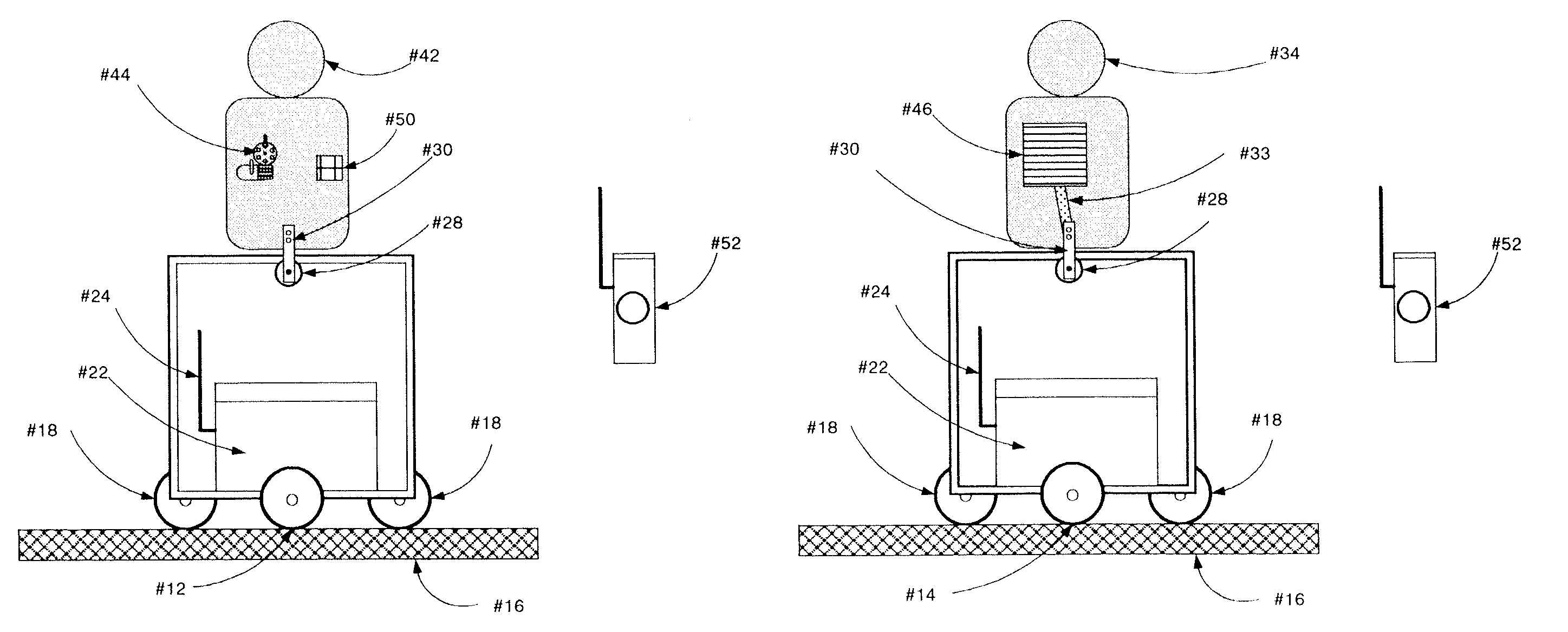
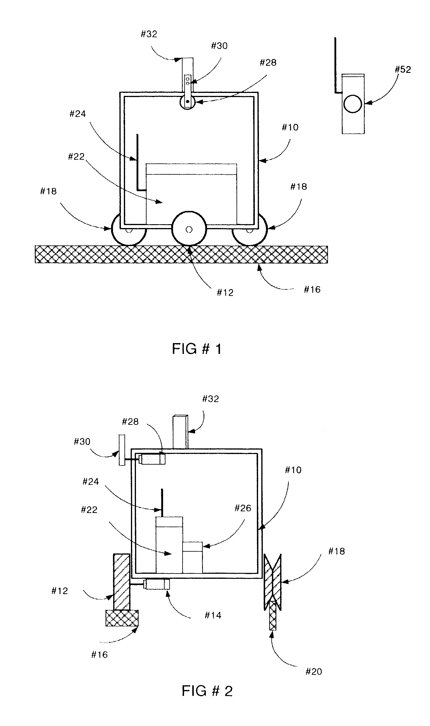
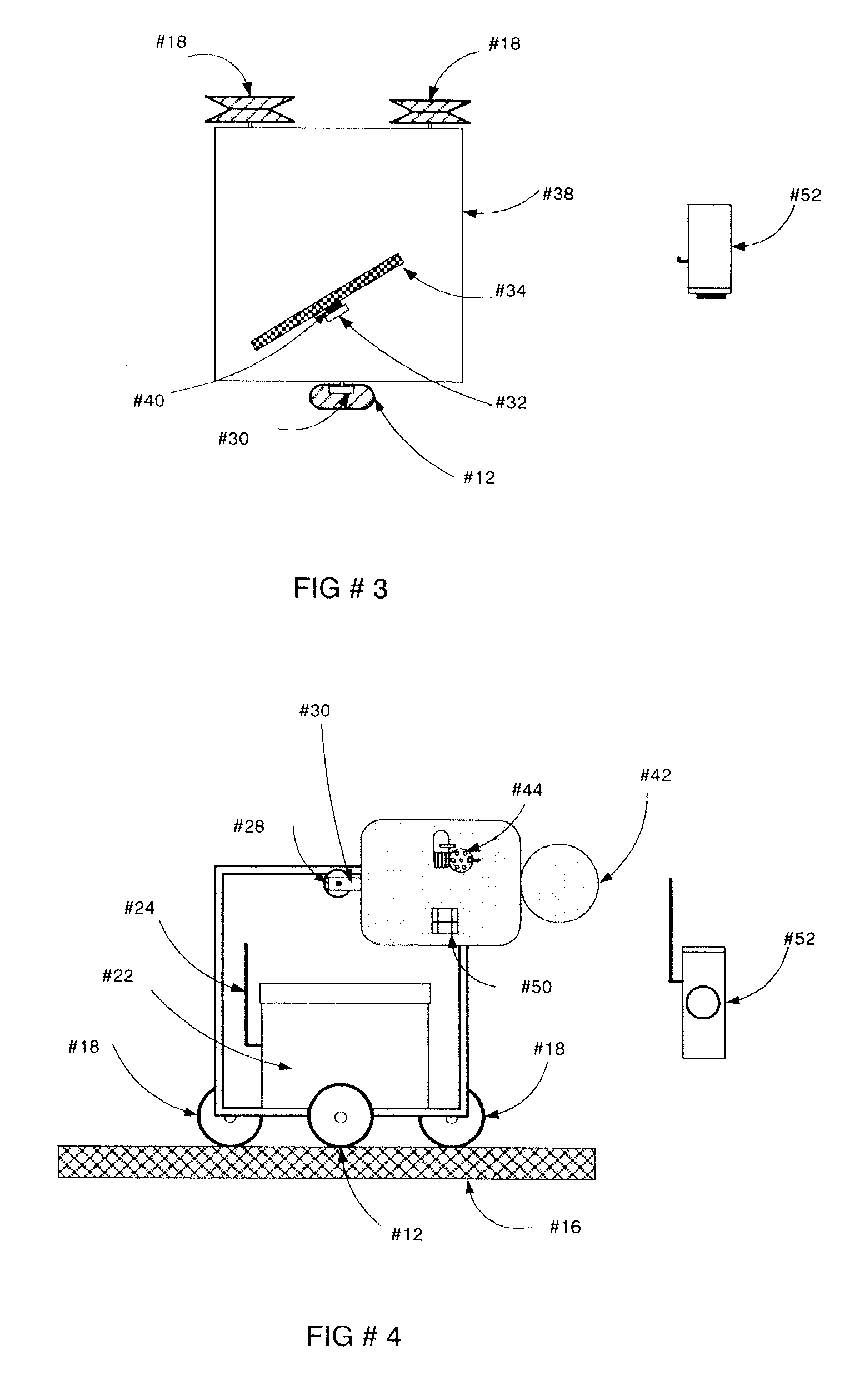
[0026]In FIG. 1 and FIG. 2, there is shown a target carriage assembly consisting of carriage frame (10) with a drive wheel (12) mounted to carriage drive motor (14). Drive motor (14) moves carriage frame (10) utilizing frictional contact with front support drive rail (16). Carriage frame (10) is maintained in a desired direction by means of stabilizing wheels (18) engaging rear support stabilizing rail (20).

[0027]Control electronics unit or electronics control unit (22) and associated remote RF antenna (24) are located within and carried by carriage frame (10). Power battery (26) is carried by carriage frame (10). Battery (26) is connected to and controlled by control electronics (22). Battery (26) provides power to all of the system components, including motor (14). Rotational target motor (28) is connected to rotational target mount arm (30) and rotates arm (30) in either direction when energized. Rotational motor (28) is controlled by control electronics (22). An angled rear targ...


PUM


Abstract

A small arms training target system including a portable, battery powered, rail guided, motor driven carriage, with stationary and moving targets connected thereto. A target-rotate control device operatively connects an electric motor and rotational arm assembly to rotate and position the target into and out of a field of view. The position is selectable by a remote control, pre-selected program, or when a sensor attached to the target is struck by a sensor. Additionally an obscuring medium is attached to the rotational arm, with a target, having on it an image of a weapon mounted behind the obscuring medium. The position of the obscuring medium is selectable to be in front of the image of a weapon, making the target a no-threat, or not in front of the target, making it a threat.

Description

BACKGROUND OF THE INVENTION[0001]1. Field of the Invention[0002]This invention relates in general to target systems and, specifically, to marksmanship and target-identification training system using moving targets.[0003]2. Description of Related Art[0004]The target systems being used to train law enforcement and military shooters today are predominantly one of the following enumerated types.[0005]A first prior art target system places a threat target image in front of the shooter and is stationary and visible at all times. Such a system has the disadvantage of allowing the shooter to constantly see the target image as a threat. There is no real-time, decisional requirement as to the threat status of the target and no dynamic indication is given to the shooter regarding their accuracy of shot placement other than by physical examination. Lastly, the target does not mimic the motions a real human person would take if they were actually shooting back.[0006]A second prior art target sys...

Claims


Application Information

Patent Timeline
Patent Type & Authority Patents(United States)
IPC IPC(8): F41J9/00
CPCF41J9/02
Inventor BLIEHALL, JAMES
Owner BLIEHALL JAMES
Why Eureka
Try Eureka