Supercharge Your Innovation With Domain-Expert AI Agents!

Automated integrated circuit clock insertion

a technology of integrated circuit clock and clock inserting, which is applied in the direction of cad circuit design, error detection/correction, instruments, etc., can solve the problems of not all of the ic design process is automated, designers are forced to rapidly develop new and more complicated ic designs, and the complexity of ic designs continues to increas

Inactive Publication Date: 2013-01-03
JUMIPER NETWORKS INC
View PDF1 Cites 0 Cited by
  • Summary
  • Abstract
  • Description
  • Claims
  • Application Information

AI Technical Summary

Benefits of technology

The patent text describes a method for automatically inserting a clock signal into an integrated circuit. The method involves retrieving location information about the components of the circuit that use a clock signal, deploying a clock mesh based on the location information, and mapping the components of the circuit to specific clock buffers. An H-tree is then connected to the components, and a clock box is generated based on the location information. The technical effects of this method include reducing the time and effort required for clock insertion and improving the accuracy and stability of the clock signal.

Problems solved by technology

As the number of components and new technologies that are incorporated into integrated circuits (ICs) continues to increase, the complexity of IC designs and the density of components fabricated into today's IC chips continue to increase.
Additionally, market pressures further challenge designers to rapidly develop new and more complicated IC designs that can be fabricated in a cost effective manner while also meeting customer requirements.
Unfortunately, despite the complexity of today's ICs, not all of the IC design process is automated and thus must still be performed manually.

Method used


Image

  • Automated integrated circuit clock insertion
  • Automated integrated circuit clock insertion
  • Automated integrated circuit clock insertion

Examples


Embodiment Construction

[0015]The following detailed description refers to the accompanying drawings. The same reference numbers in different drawings may identify the same or similar elements. Also, the following detailed description does not limit the invention.

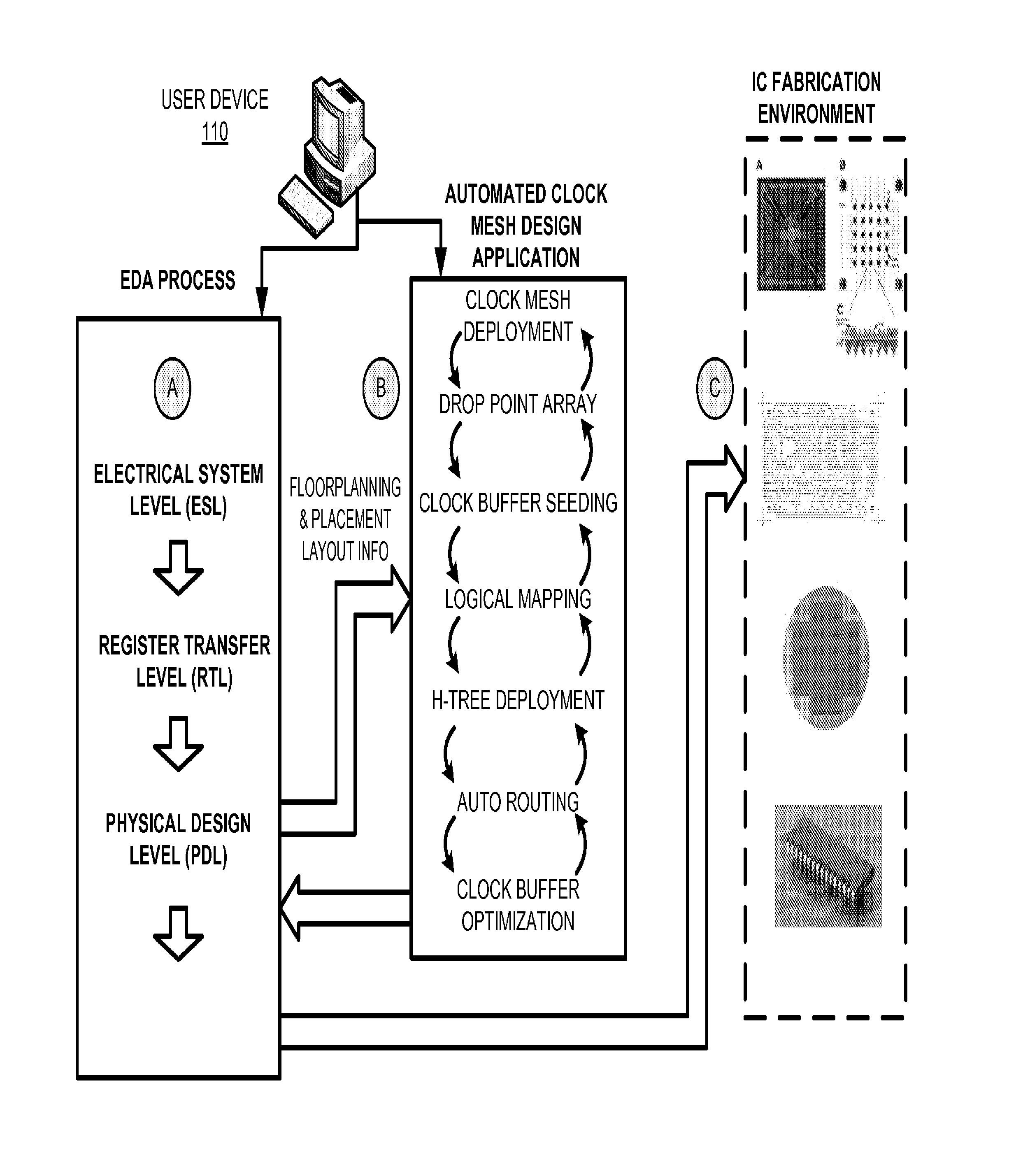
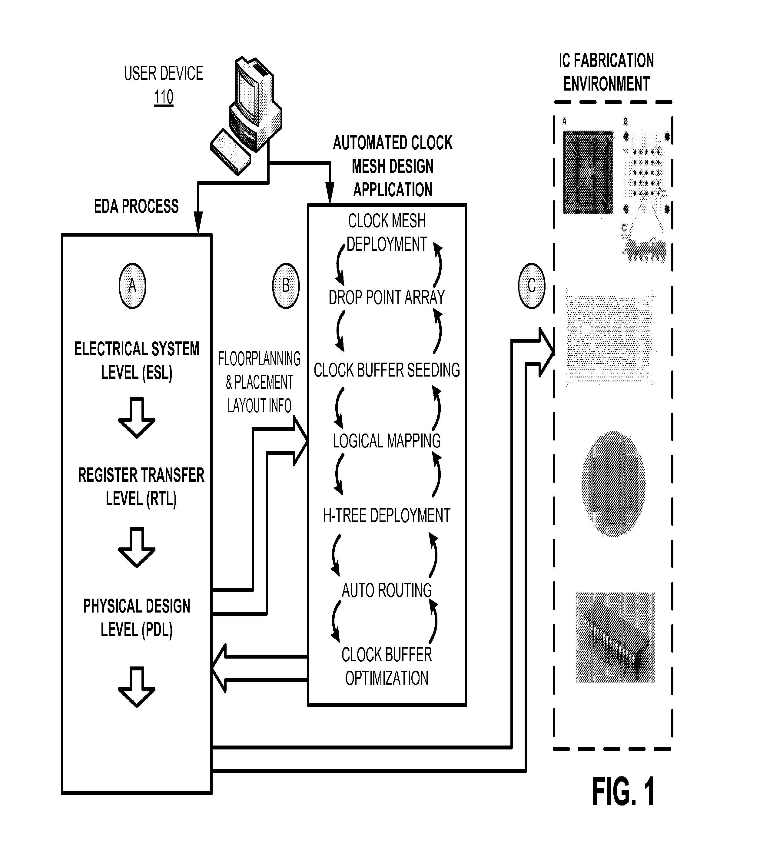
[0016]An implementation described herein may include systems and / or methods that provide for an automated integrated circuit clock insertion using a technique that can automate a clock insertion operation, within an integrated circuit (IC) design process, to reduce or eliminate clock skew and / or clock latency within an IC. Additionally, or alternatively, the automated IC clock insertion may reduce the time to design, to troubleshoot, and / or to perform design revisions, associated with clock distribution within an IC, which may reduce the cost associated with IC design, development, and / or fabrication.

[0017]As described herein, a clock mesh may be utilized to reduce the clock skew and / or clock latency in an IC. More particularly, distributing a clo...


PUM


Abstract

A user device receives a request to perform an automatic clock insertion operation for an integrated circuit; retrieves location information regarding a group of components, of the integrated circuit, that use a clock signal; deploys a clock mesh based on the location information regarding the group of components; and inserts drop points into the clock mesh; deploys a particular buffer for a particular drop point; maps a component, of the group of components, to the particular buffer; generates a clock box for the particular buffer, where dimensions of the clock box are based on a location of the component; deploys an H-tree for the clock box, where dimensions of the H-tree are proportional to the clock box dimensions; connects the H-tree to the component; and displays or stores clock mesh information, information regarding the group of buffers, information regarding the H-tree, and the location information regarding the group of components.

Description

BACKGROUND[0001]As the number of components and new technologies that are incorporated into integrated circuits (ICs) continues to increase, the complexity of IC designs and the density of components fabricated into today's IC chips continue to increase. Some of today's large ICs have over one billion transistors, installed on a chip of approximately 300 square millimeters, with component densities exceeding one million transistors per square millimeter. Client demands challenge designers to find new ways to come up with faster and more capable IC devices that require increasingly complicated IC designs. Additionally, market pressures further challenge designers to rapidly develop new and more complicated IC designs that can be fabricated in a cost effective manner while also meeting customer requirements. Unfortunately, despite the complexity of today's ICs, not all of the IC design process is automated and thus must still be performed manually.SUMMARY[0002]According to one aspect,...

Claims


Application Information

Patent Timeline
Patent Type & Authority Applications(United States)
IPC IPC(8): G06F17/50
CPCG06F2217/62G06F17/5068G06F30/396G06F30/39
Inventor SIDDIQUI, KHALIL
Owner JUMIPER NETWORKS INC
Features
  • R&D
  • Intellectual Property
  • Life Sciences
  • Materials
  • Tech Scout
  • Unparalleled Data Quality
  • Higher Quality Content
  • 60% Fewer Hallucinations
Learn More