
Hydraulic Actuator Device for Raising and Lowering a Seat and Lid

a technology of hydraulic actuators and toilet seats, which is applied in the direction of bathroom accessories, domestic applications, applications, etc., can solve the problems of poor hygiene, contamination of the lid, and displeasure of other users of the toil

Inactive Publication Date: 2013-01-10
GOMEZ ESPANA COLLIGNON CARLO
View PDF0 Cites 9 Cited by
  • Summary
  • Abstract
  • Description
  • Claims
  • Application Information

AI Technical Summary

Benefits of technology

The present invention provides a hydraulic drive device for automatically raising and lowering the toilet covering lid and seat to avoid using hands and prevent wetting the seat with urine. This device offers greater safety and hygiene to toilet users, avoids the possibility of infection, and is easy to manufacture, drive, and install. Additionally, the device allows the user to lift the lid and seat by hand if needed.

Problems solved by technology

When a female person uses the toilet, she usually tends to lift the lid with her hands or with at least with one hand, which can lead to contamination, poor hygiene, etc.
However, in many cases men, when the lid is covering the bowl hole, just lift the lid, or if the lid is lifted, no longer finds it necessary to lift the seat, which when they urinate, leads to splashing and wetting with the seat with urine, causing displeasure to other users of the toilet and causing contamination of the lid that could be a source of infection for other users.
None of the aforementioned documents protect or disclose a hydraulic drive device for automatically raising and lowering the toilet covering lid and seat and using the same fluid source used to fill the elevated tank and to dislodge the excreta down the drain, wherein said device is of a simple structure, easy installation and easy operation that may be activated by sensors or by manual driving buttons or by the feet.

Method used


Image

  • Hydraulic Actuator Device for Raising and Lowering a Seat and Lid
  • Hydraulic Actuator Device for Raising and Lowering a Seat and Lid
  • Hydraulic Actuator Device for Raising and Lowering a Seat and Lid

Examples


Embodiment Construction

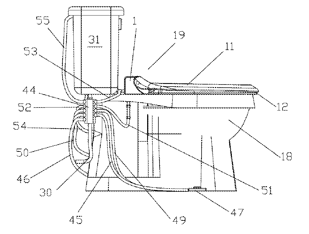
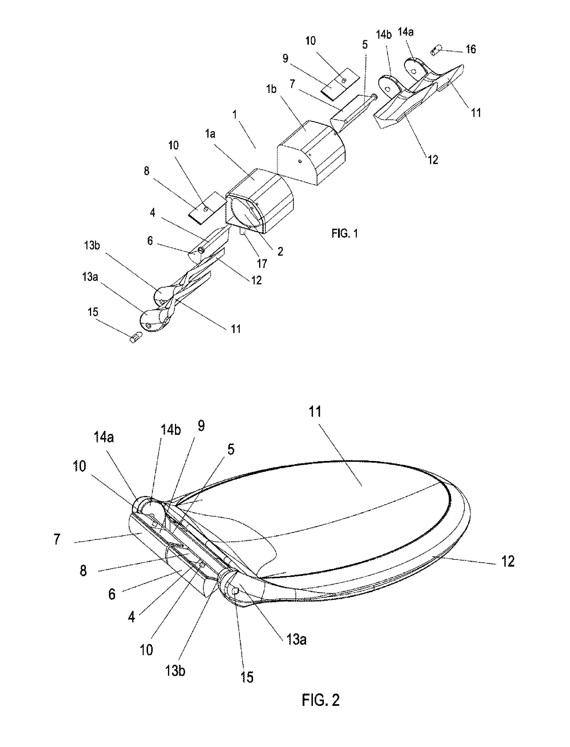
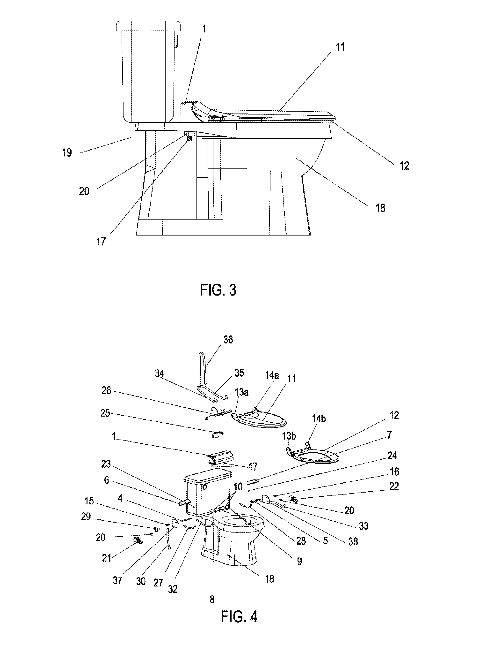
[0065]The characteristic details of the hydraulic drive device for raising and lowering the toilet covering lid and seat, is clearly shown in the following description and the appended illustrative drawings, serving the same reference signs to indicate the same parts.

[0066]Referring to FIG. 1 shows an exploded view of the hydraulic drive device for raising and lowering the toilet covering lid and seat in accordance with the present invention. In said figure the device comprises a housing 1 comprising two modules 1a and 1b, a left module 1a and a right module 1b, both modules are adapted to engage each other, the housing already assembled defines a left hollow chamber 2 and a right hollow chamber 3 (not shown) in semicircular shape, adapted to receive a left rotating shaft and a right rotating shaft 5, and to accommodate a left counterweight 6 and a right counterweight 7, respectively. Said shafts are fixed within the chambers with a rotating motion capacity; each of the chamber 2 an...


PUM


Abstract

The present invention generally relates to means and devices used in toilets or lavatories; particularly relates to means used for automatically raise and lower the toilet covering lids and more specifically relates to a hydraulic drive device for raising and lowering the covering lid and seat of the toilet hole; characterized in that comprises a housing that comprises two adjoining hollow chambers, one left and one right, the chambers housing a left rotating shaft and a right rotating shaft, respectively; both shafts comprise a fixed counterweight that can rotate along with the shaft inside the chambers; each chamber also houses a left elastic diaphragm and a right one, adjoined and interacting with the counterweights; said diaphragms comprising at least one connecting pivot wherein a inlet and / or outlet working fluid duct is connected so as to drive-push the counterweights when are inflated with working fluid supplied by an automatic system or by a contact driving elements system, and causing the swinging of said shafts connected to a toilet lid and seat, respectively, and which comprise in the back part a left connection flange and a right one with orifice, through which a left fixing bolt is inserted and a right one, fixed to the ends of the rotating shafts with the corresponding counterweights.

Description

FIELD OF THE INVENTION[0001]The present invention generally relates to means and devices used in toilets or lavatories, and particularly relates to means used for automatically raising and lowering the toilet covering lids and, more specifically, relates to a hydraulic drive device for raising and lowering the covering lid and seat of a toilet.BACKGROUND OF THE INVENTION[0002]Is well known that toilets are commonly shaped in such a way that structurally comprise a bowl consisting of a body with a central hollow round or oblong hole, with an internal trap that discharges to a base fixed to the floor where the exit of the trap is connected to the sanitary drainage network, said bowl comprises an upper tank where a volume of water is deposited, which is connected through a duct to said bowl, wherein said ducts comprise a ball-cock supply valve with actuating means for discharging water into the bowl.[0003]A water supply duct from a water supply source of a domestic network or public ne...

Claims


Application Information

Patent Timeline
Patent Type & Authority Applications(United States)
IPC IPC(8): A47K13/10
CPCA47K13/10
Inventor GOMEZ-ESPANA COLLIGNON, CARLO
Owner GOMEZ ESPANA COLLIGNON CARLO
Learn More