Motor assembly for vehicle air conditioner

a technology for motor components and air conditioners, which is applied in the direction of positive displacement liquid engines, liquid fuel engines, piston pumps, etc., can solve the problems of control circuit devices wet,

Active Publication Date: 2006-08-31
DENSO CORP
View PDF6 Cites 16 Cited by
  • Summary
  • Abstract
  • Description
  • Claims
  • Application Information

AI Technical Summary

Benefits of technology

[0009] Accordingly, it is an objective of the present invention to provide a motor assembly for a vehicle air conditioner, which assembly prevents an integrally assembled control circuit device from being wet.
[0010] To achieve the above objective, the present invention provides a motor assembly for a vehicle air conditioner. The motor assembly includes a motor having a rotary shaft, a control circuit device that controls the motor to rotate, a fan fixed to the rotary shaft, a motor holder for accommodating the motor, a lower case attached to the motor holder. The motor holder or the lower case defines therein a circuit accommodating chamber for accommodating the control circuit device. A side wall of the motor holder or the lower case that defines the circuit accommodating chamber has a vent for ventilating the circuit accommodating chamber. A boundary section is formed between the motor holder and the lower case. An overhang extends from the motor holder. The overhang is integrally formed with the motor holder. The overhang faces an outer surface of the side wall of the lower case. In a section of the circumference of the lower case, the overhang continuously covers the boundary section along the outer surface of the side wall of the lower case. A bulging portion projects from the overhang in a direction away from the motor holder. The bulging portion is arranged to prevent water droplets from reaching the vent from the overhang.

Problems solved by technology

Therefore, if water fails to be guided to the outside of the assembly through the notch, the water can enter the interior of the motor and cause the control circuit device to be wet.
Further, water that exits the assembly through the boundary section can flow along the outer surface of the motor holder or the lower case, and enter the motor through the hole, causing the control circuit device to be wet.
Further, water that exits the assembly through the boundary section between the blower case and the motor holder can flow along the outer surface of the motor holder, and enter the interior through the boundary section between the motor holder and the lower case, causing the control circuit device to be wet.
This causes connecting members such as wires that electrically connect the control circuit device with the motor to be wet with water droplets.
Further, in some cases condensation occurs due to the difference between the temperature of the passenger compartment and the outside temperature, which can result in water droplets collected on the connecting members.

Method used


Image

  • Motor assembly for vehicle air conditioner
  • Motor assembly for vehicle air conditioner
  • Motor assembly for vehicle air conditioner

Examples


Embodiment Construction

[0020] One embodiment of the present invention will now be described with reference to the drawings.

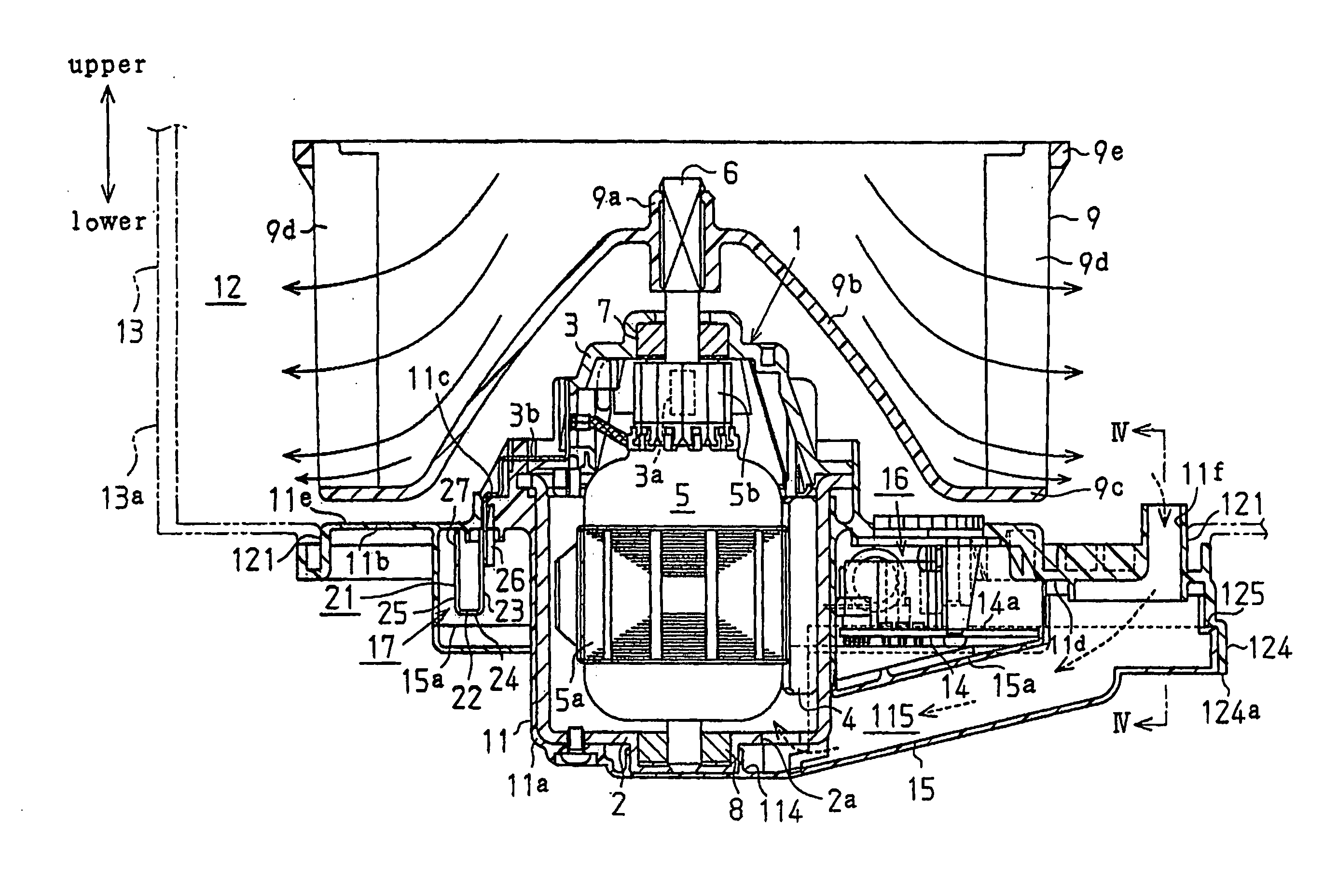
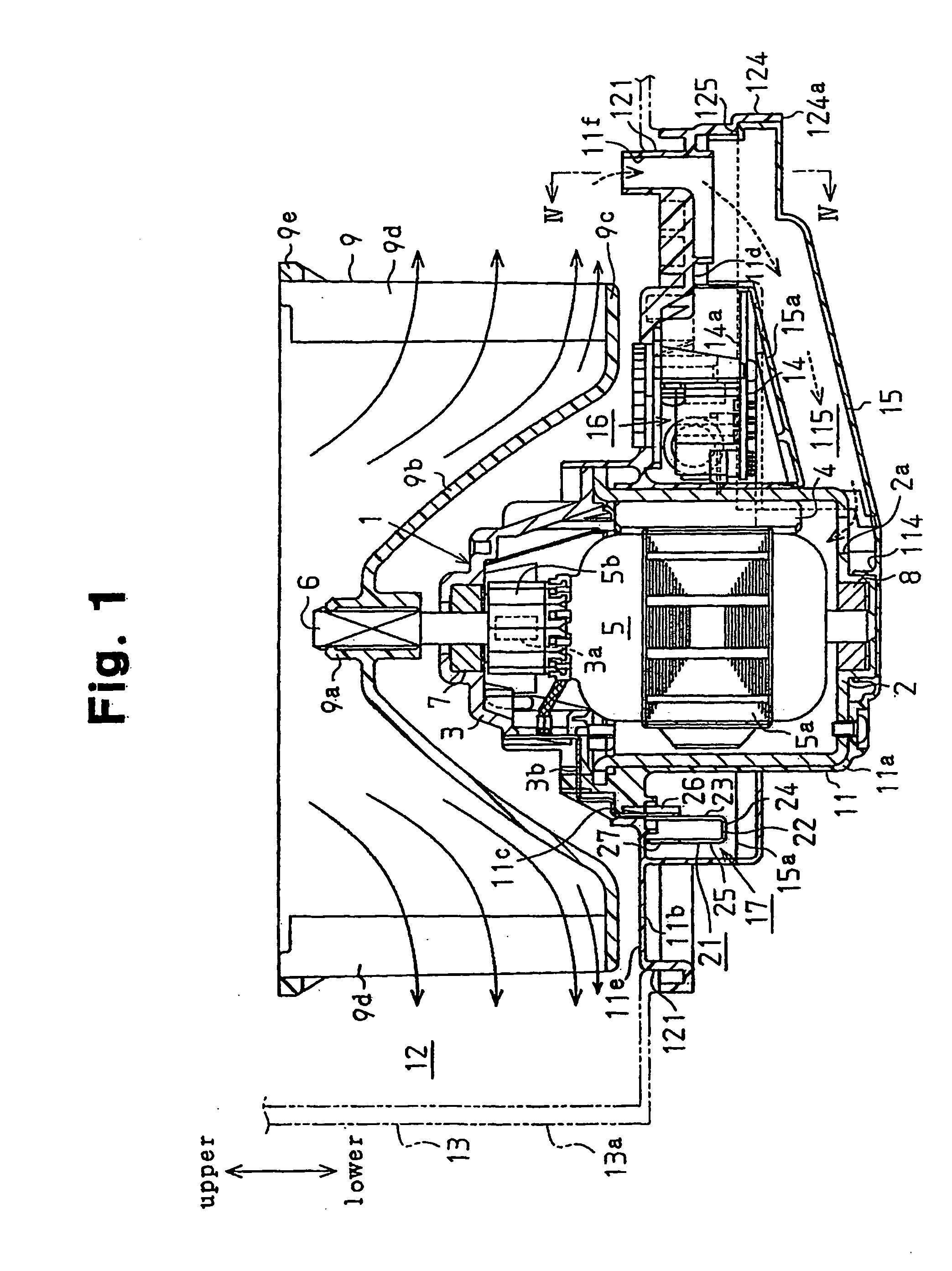
[0021] As shown in FIG. 1, a motor 1 of a motor assembly for a vehicle air conditioner is a direct-current motor. The motor 1 includes a substantially cylindrical yoke 2, a brush holder 3, magnets 4 and an armature 5. The brush holder 3 covers an open end (upper end as viewed in FIG. 1) of the yoke 2 and holds brushes 3a. The magnets 4 are secured to the inner circumferential surface of the yoke 2. The armature 5 is substantially accommodated in the yoke 2. A rotary shaft 6 of the armature 5 is rotatably supported with a bearing 7 fixed to the brush holder 3 and with a bearing 8 fixed to the yoke 2 such that one end of the rotary shaft 6 protrudes upward from the brush holder 3. The motor 1 is arranged in the vehicle such that the axial direction of the rotary shaft 6 is substantially vertical.

[0022] The armature 5, which is located inside the magnets 4, has a core 5a and a commutat...


PUM


Abstract

A motor holder or a lower case defines therein a circuit accommodating chamber for accommodating a control circuit device. A side wall of the motor holder or the lower case that defines the circuit accommodating chamber has a vent for ventilating the chamber. A boundary section is formed between the motor holder and the lower case. An overhang extends from the motor holder. In a section of the circumference of the lower case, the overhang continuously covers the boundary section along the outer surface of the side wall of the lower case. A bulging portion is arranged to prevent water droplets from reaching the vent from the overhang. Therefore, the motor assembly prevents the integrally assembled control circuit device from being wet.

Description

RELATED APPLICATIONS [0001] This application is a divisional of U.S. application Ser. No. 10 / 875,399, filed Jun. 23, 2004. This application also claims foreign priority benefits from Japanese Patent Application Serial No. 2003-184112, filed Jun. 27, 2003 and Japanese Patent Application Serial No. 2003-271368, filed Jul. 7, 2003.BACKGROUND OF THE INVENTION [0002] The present invention relates to a motor assembly for a vehicle air conditioner, which assembly includes a motor and a control circuit device integrally assembled with the motor. More particularly, the present invention pertains to a motor assembly for a vehicle air conditioner, which assembly has a structure that prevents a control circuit device from being wet. [0003] For example, Japanese Patent No. 3157567 discloses a motor assembly for a vehicle air conditioner, which assembly includes a motor and a fan. The motor drives rotary shaft that protrudes upward. The fan is coupled to the rotary shaft. As the rotary shaft rota...

Claims


Application Information

Patent Timeline
Patent Type & Authority Applications(United States)
IPC IPC(8): H02K11/00H02K5/10F04B17/00F04D25/08H02K5/20H02K5/22H02K7/14H02K9/06H02K11/04
CPCF04D25/082H02K5/10H02K5/225H02K9/06H02K11/0073H02K11/33F04D29/5806
Inventor NODA, TAKEOSUZUKI, AKIHIKO
Owner DENSO CORP
Why Eureka
Try Eureka