Fuel injection nozzle for an internal combustion engine with direct fuel injection

a technology of fuel injection nozzle and internal combustion engine, which is applied in the direction of fuel injection apparatus, spraying apparatus, charge feed system, etc., to achieve the effect of improving the combustion of fuel in the engine, and increasing the atomization of fuel in the combustion chamber

Inactive Publication Date: 2005-07-14
DAIMLER AG
View PDF6 Cites 18 Cited by
  • Summary
  • Abstract
  • Description
  • Claims
  • Application Information

AI Technical Summary

Benefits of technology

[0012] In one embodiment of the invention, in, or respectively, immediately in front of, the sealing surface of the nozzle seat a turbulence chamber in the nozzle seat and in, or respectively, immediately in front of, the sealing surface of the closure body another turbulence chamber is provided so that two turbulence chamber is arranged so that two turbulence chambers are arranged during a particular operating position of the fuel injection nozzle relative to the jet axis opposite one another. By the arrangement of two chambers in, or respectively, in front of, the seal area, the turbulence of the nozzle flow in the gap area between the nozzle seat and the closure member is increased so that the fuel atomization is also increased. In this way, manufacturing tolerances can be compensated for, that is, the flow behavior of the fuel ejected from the fuel injection nozzle is little affected by the manufacturing tolerances.
[0013] In another embodiment of the invention at least one turbulence chamber is provided in, or respectively, immediately ahead of, the sealing surface of the nozzle seat and in, or respectively, directly ahead of, the sealing surface of the closure member in such a way that two turbulence chambers are arranged in a particular operating position displaced relative to the jet axis. Also, in this way, the atomizing of the fuel in the combustion chamber is increased whereby the combustion of the fuel in the engine is further improved.
[0014] In another embodiment of the invention, two turbulence chambers are provided in the gap area between the nozzle seat and the closure body in, or immediately ahead of, the seal area of the nozzle seat. With this measure, the droplets in the interior of the injected fuel cone are further atomized and their penetration to the piston surface is prevented. This measure is particularly advantageous for a stratified charge combustion process since the fuel is injected late during the compression stroke and the wetting of the piston with fuel must be prevented.
[0015] In another embodiment of the invention, two turbulence chambers are arranged at the nozzle seat and the closure member of the fuel injection nozzle in, or respectively, immediately ahead of, the seal area of the nozzle seat and at least two turbulence chambers are provided in, or respectively, immediately ahead of, the seal area of the closure member, one after the other in the stroke direction of the closure member such that two turbulence chambers are arranged opposite one another during operation of the fuel injection nozzle. In this way, the atomization of the fuel droplets is further increased. With the controlled turbulence generation in the whole area of the injected fuel jet, turbulence differences caused by manufacturing tolerances are subdued and the desired jet configuration is approximated. Alternatively, the turbulence chambers arranged at the closure member can be so formed that, in an operating position, two respective chambers are displaced relative to the jet axis.
[0016] In another embodiment of the invention, the turbulence chamber, provided in, or respectively immediately ahead of, the seal surface of the nozzle seat and / or in, or respectively immediately ahead of, the seal surface of the closure member have the form of a groove extending circumferentially around the seal surface areas. In this way, increased turbulence is achieved in the fuel flow all around the fuel cone whereby the breakup of the laminar fuel flow is reinforced and consequently smaller droplets are injected into the combustion chamber.
[0017] The measures referred to above are used preferably in connection with injection nozzles for internal combustion engines with spark ignition wherein the fuel is injected in the form of a hollow cone, and particularly in connection with a stratified charge combustion process. In such internal combustion engines, the fuel is so injected that, at the end of the hollow fuel cone, a torus-shaped swirl is formed and the spark plug is arranged in the combustion chamber of the engine so that the electrodes of the spark plug disposed outside the fuel cone extend from the outside into the torus-shaped cone. With the arrangement of the turbulence chambers in or, respectively, immediately ahead of, the seal areas of the nozzle seat, the turbulence is increased specifically in the outer area of the injected fuel cone whereby the formation of the torus-shaped edge swirl is more distinct. In jet-controlled or a stratified charge combustion, the necessary symmetry of the torus-shaped swirl is maintained by the fuel injection nozzle according to the invention and a tilting of the swirl is prevented. As a result, ignition failures are avoided.

Problems solved by technology

However, the fuel injectors are subject to certain manufacturing variations which results in different injection jet formations.

Method used


Image

  • Fuel injection nozzle for an internal combustion engine with direct fuel injection
  • Fuel injection nozzle for an internal combustion engine with direct fuel injection
  • Fuel injection nozzle for an internal combustion engine with direct fuel injection

Examples


Embodiment Construction

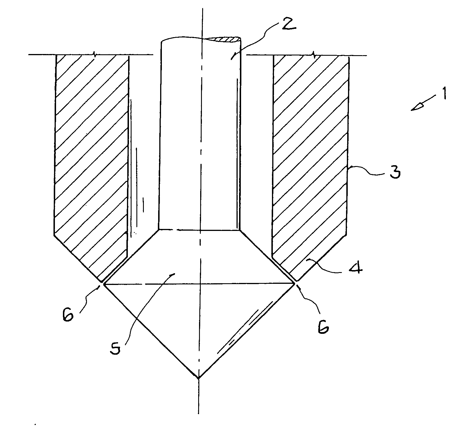
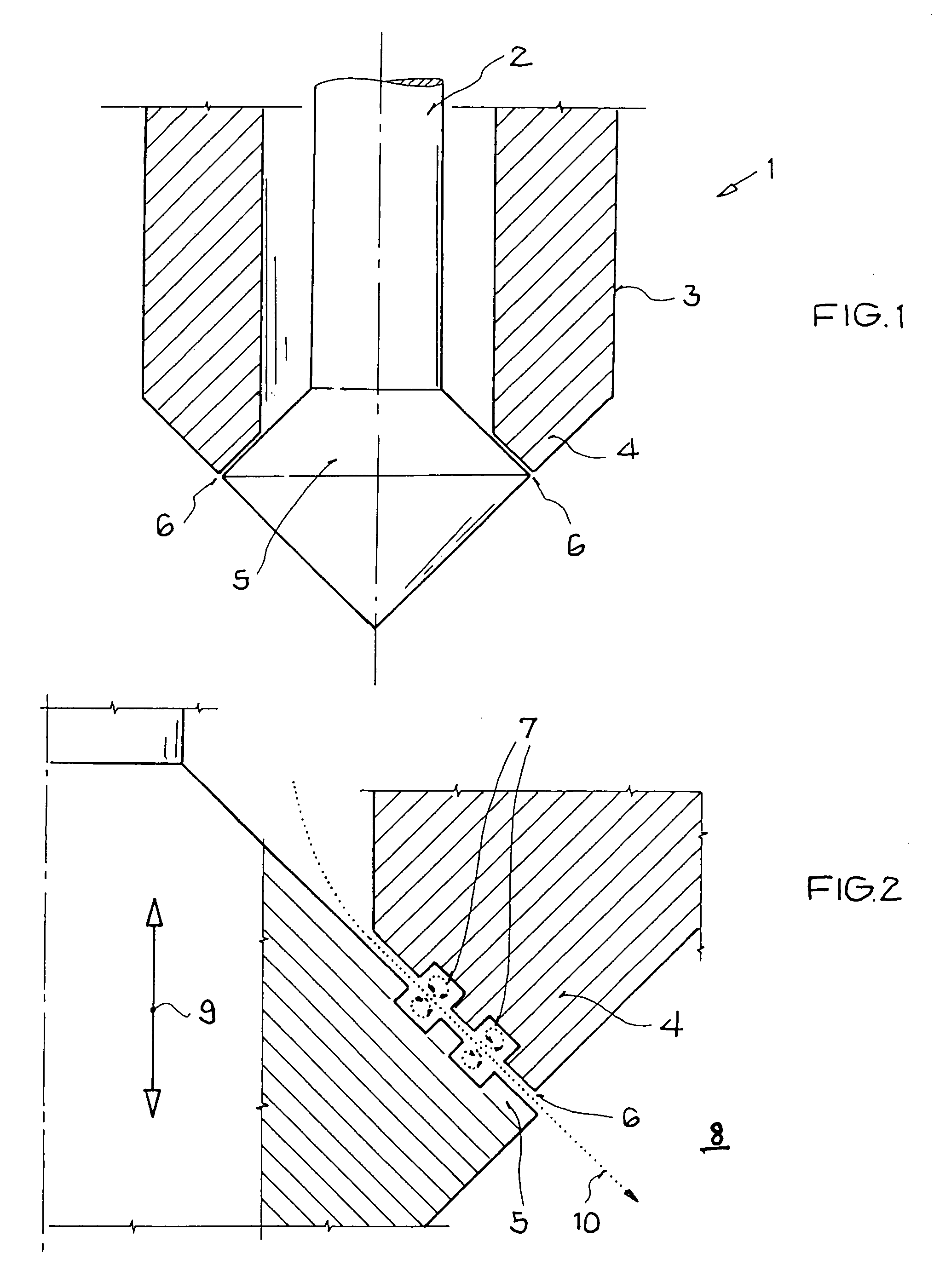
[0031]FIG. 1 shows a fuel injection nozzle 1 with a nozzle needle 2 and a closure member 5 disposed in a housing 3 of the fuel injection nozzle 1, In the area of the combustion chamber the nozzle 1 includes a nozzle seat 4, which is engaged by the closure member 5 when the nozzle is closed. The closure member 5 is connected at its upper end via the nozzle needle 2 to an operating mechanism which is not shown in the figures as it is conventional. Preferably, a piezo-actuator is used in the operating mechanism which expands when subjected to an electrical voltage providing for an operating stroke of the closure member 5 corresponding to the voltage applied. The fuel injection nozzle, that is, the closure member 5 is biased into a sealing position by a return spring which is not shown. The closure member 5 is moved to an operating position by way of the nozzle needle 2 such that a gap 6 is established between the closure member 5 and the nozzle seat 4.

[0032] As shown in FIG. 2, the cl...


PUM


Abstract

In an injection nozzle for an internal combustion engine including a nozzle housing, a closure member disposed in a nozzle opening and connected to a nozzle needle for axially moving the closure member outwardly off its seat in the nozzle opening to open the nozzle by providing a gap to permit fuel to be discharged into a combustion chamber of an internal combustion engine so as to form a fuel injection cone, the nozzle seal and the closure member have seal surface areas provided with turbulence chambers for imparting turbulence to the fuel flowing through the gap in order to more finely atomize the fuel forming the fuel cone in the combustion chamber.

Description

[0001] This is a Continuation-In-Part Application of International Application PCT / EP2003 / 006985 filed Jul. 1, 2003 and claiming the priority of German Application 102 31 583.3 filed Jul. 11, 2002.BACKGROUND OF THE INVENTION [0002] The invention resides in a fuel injection nozzle for an internal combustion engine with direct fuel injection including a nozzle housing with a nozzle seat, a nozzle needle with a conical closure body which, in its closed position, engages a seal surface formed on the nozzle seat but is movable axially outwardly by the nozzle needle for opening the nozzle to form a gap through which a hollow conical fuel jet is discharged from the nozzle into a combustion chamber of the engine. [0003] In the operation of new spark ignition internal combustion engines with direct fuel injection the mixture formation in the combustion chambers has been improved by the use of modern fuel injection nozzles wherein, however, manufacturing tolerances affect the combustion and t...

Claims


Application Information

Patent Timeline
Patent Type & Authority Applications(United States)
IPC IPC(8): F02M61/08F02M61/16F02M61/18
CPCF02M61/08F02M61/1873F02M61/162
Inventor KADEN, ARNOLDKRUGER, CHRISTIANSTEIL, OLIVER
Owner DAIMLER AG
Why Eureka
Try Eureka