Additive printed mask process and structures produced thereby

a printing mask and additive technology, applied in the field of additive printing mask process and the structure produced by it, can solve the problem of less control of target materials, and achieve the effect of preventing the wetting of material abutting

Inactive Publication Date: 2008-04-29
PALO ALTO RES CENT INC
View PDF20 Cites 15 Cited by
  • Summary
  • Abstract
  • Description
  • Claims
  • Application Information

AI Technical Summary

Benefits of technology

[0013]According to one aspect of the invention, a mask pattern is formed by digital lithography on the surface of a substrate. The mask pattern is formed to include gaps which are equal in width to the desired width of the final feature to be formed (the target feature). This is possible, since digital lithography systems are capable of controllably depositing droplets with an inter-droplet spacing less than a droplet diameter. A target material is deposited over (or between) the mask, by digital lithography, capillary action or other appropriate method. While the mask material is well controlled in terms of dispersion, wetting, etc., the target material is less well controlled. The target material fills the gaps formed in the mask. The mask acts as a form for the target material, overcoming issues associated with controlling the deposition of the target material. The target material may then be cured or hardened, if necessary, and the mask removed, producing the target feature.
[0015]According to another aspect of the present invention, the target feature is formed of layers of target material, each layer having a desired property. For example, a multi-layered target feature may be comprised of layers of hydrophilic material below layers of hydrophobic material. Such a target structure is useful in preventing the wetting of material abutting against the target structure, for example the spreading of a first fluid from one lateral side of the structure over its top and onto the opposite lateral side of the structure.

Problems solved by technology

While the mask material is well controlled in terms of dispersion, wetting, etc., the target material is less well controlled.

Method used


Image

  • Additive printed mask process and structures produced thereby
  • Additive printed mask process and structures produced thereby
  • Additive printed mask process and structures produced thereby

Examples


Embodiment Construction

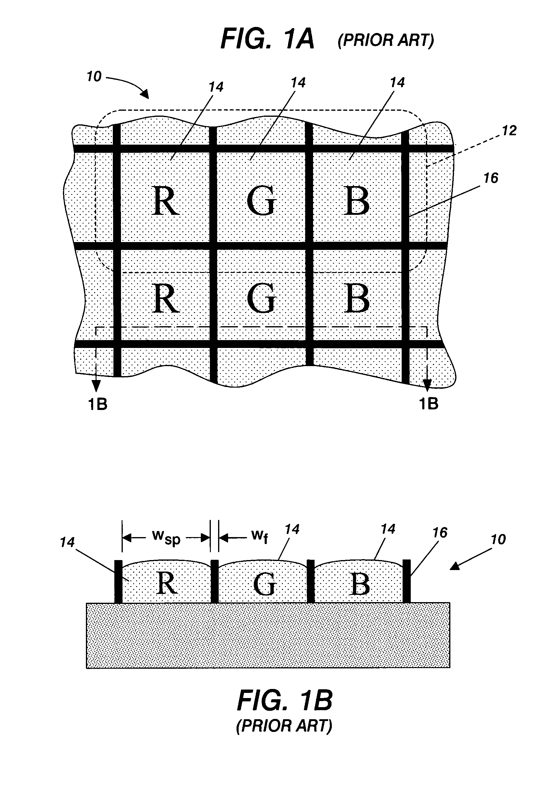
[0040]With reference initially to FIGS. 1A and 1B, there is shown therein a structure of the type formed by one embodiment of the present invention. FIGS. 1A and 1B are illustrations of a portion of a color filter 10 for a plat-panel display. As mentioned, such a filter comprises a number of pixels 12, each pixel being composed of three or more sub-pixels 14. The actual geometry of the sub-pixels, such as triangular, striped, diagonal, etc. is not critical to the operation of the present invention, but will be discussed in further detail below. Sub-pixels 14 are each primarily transparent to a specific color of light, such as red, green or blue. The individual sub-pixels 14 are separated by a pixel frame 16. Pixel frame 16 is composed of a number of horizontal and vertical elements which form cavities, shown in FIG. 1B, for the receipt of material forming sub-pixels 14. For reference, it will be assumed that the width wsp of each sub-pixel is on the order of 25 to 30 μm and the widt...


PUM

PropertyMeasurementUnit
diameteraaaaaaaaaa
widthaaaaaaaaaa
widthaaaaaaaaaa

Abstract

A digital lithographic process first deposits a mask layer comprised of print patterned mask features. The print patterned mask features define gaps into which a target material may be deposited, preferably through a digital lithographic process. The target material is cured or hardened, if necessary, into target features. The mask layer is then selectively removed. The remaining target features may then be used as exposure or etch masks, physical structures such as fluid containment elements, etc. Fine feature widths, narrower the minimum width of the print patterned mask features, may be obtained while realizing the benefits of digital lithography in the manufacturing process.

Description

CROSS-REFERENCE TO RELATED APPLICATIONS[0001]The present invention is related to copending U.S. Application for Letters Patent titled “Process For Forming A Feature By Undercutting A Printed Mask” by Limb et al., Ser. No. 11 / 336,365, filed on Jan. 20, 2006 and assigned to the same assignee as the present application, and further which is hereby incorporated herein by reference.BACKGROUND OF THE INVENTION[0002]1. Field of the Invention[0003]This invention relates generally to electronic device fabrication processes, and more particularly to a method of employing a printed mask to form features narrower than the printed mask feature width.[0004]2. Description of the Prior Art[0005]Digital lithography is a maturing technology designed to reduce the costs associated with photolithographic processes, used often in the fabrication of micro-electronic devices, integrated circuits, and related structures. Digital lithography directly deposits patterned material onto a substrate in place of ...

Claims


Application Information

Patent Timeline
Patent Type & Authority Patents(United States)
IPC IPC(8): H01L21/31G03F1/92
CPCB41M3/003B41M3/006G02F1/133512G02F1/133516G03F7/2018Y10S438/942
Inventor WONG, WILLIAMLIMB, SCOTTCHABINYC, MICHAELRUSSO, BEVERLYLUJAN, RENE A.
Owner PALO ALTO RES CENT INC
Why Eureka
Try Eureka