Shock and impact testing device and method

a testing device and impact technology, applied in the direction of material strength using tensile/compressive forces, instruments, structural/machine measurement, etc., can solve the problems of wasting a lot of time during testing and shortened the lifetime of the shock and impact testing devi

Inactive Publication Date: 2013-01-10
HONG FU JIN PRECISION IND (SHENZHEN) CO LTD +1
View PDF2 Cites 7 Cited by
  • Summary
  • Abstract
  • Description
  • Claims
  • Application Information

AI Technical Summary

Problems solved by technology

Thus, much time may be wasted during test and the lifetime of the shock and impact testing device may be shortened because of the repeated impact process.

Method used


Image

  • Shock and impact testing device and method
  • Shock and impact testing device and method
  • Shock and impact testing device and method

Examples


Embodiment Construction

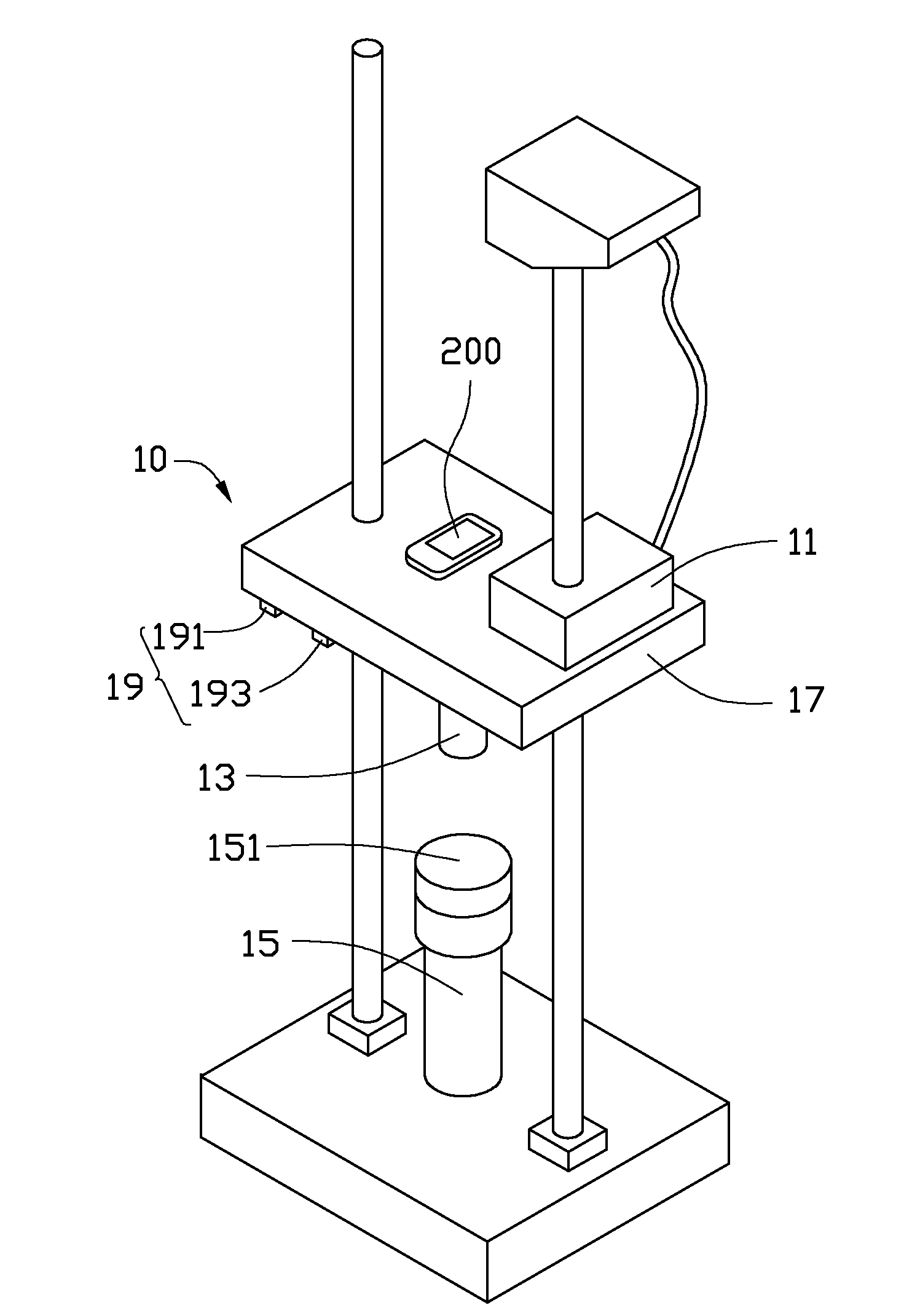
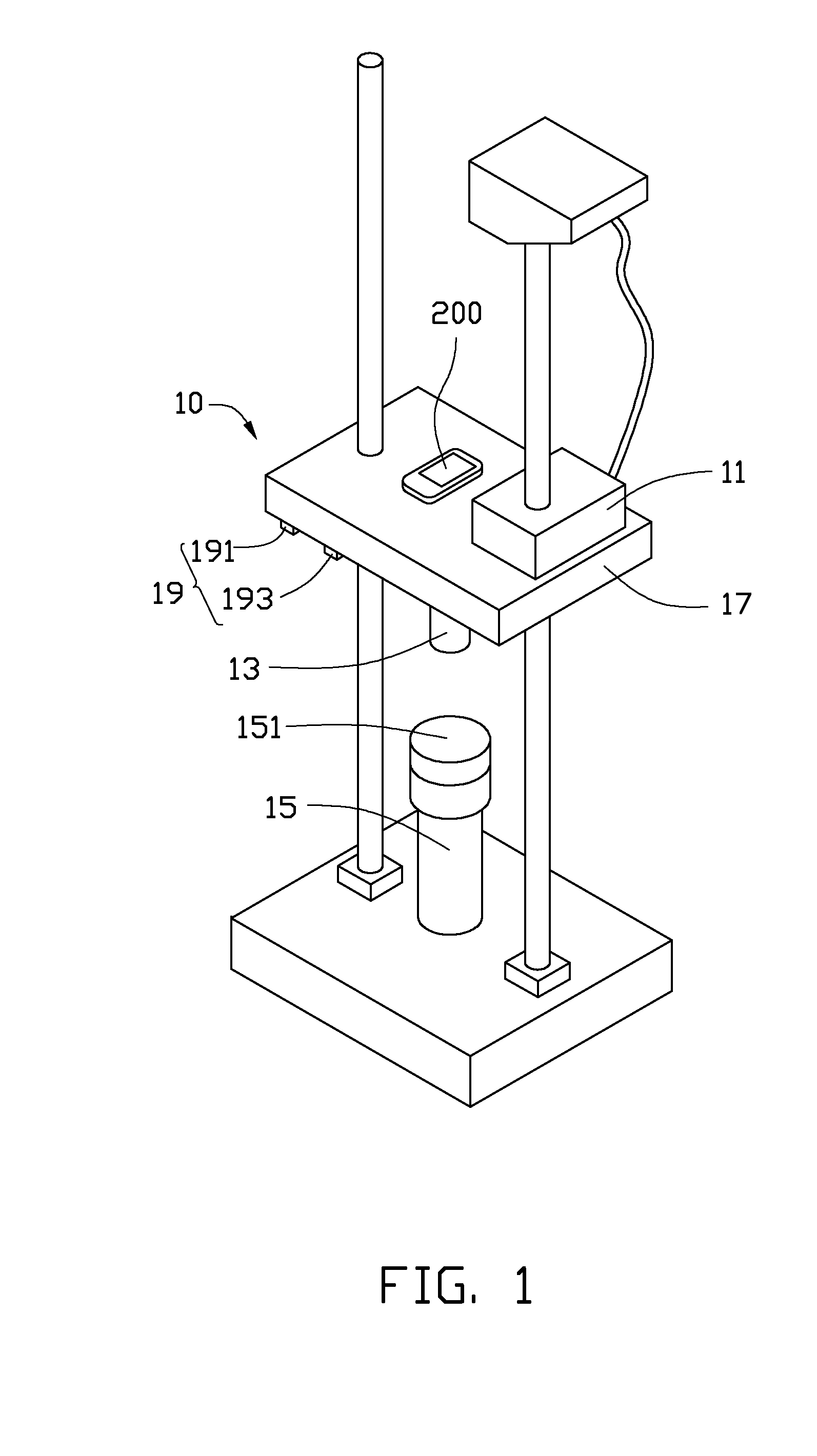
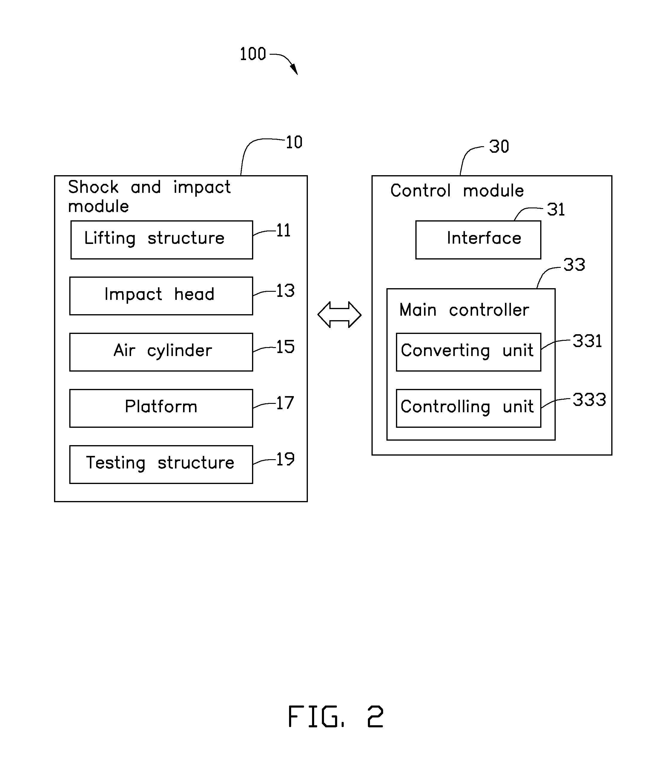
[0011]Referring to FIGS. 1 and 2, an exemplary embodiment of shock and impact testing device 100 includes a shock and impact module 10 and a control module 30 electrically connected to the shock and impact module 10. The control module 30 receives impact parameters, computing the impact parameters to get testing parameters, and drives the shock and impact module 10 to execute shock and impact testing for an electronic device 200 according to the testing parameters.

[0012]The shock and impact module 10 includes a lifting structure 11 (schematically shown), an impact head 13, an air cylinder 15, a platform 17 secured to the lifting structure 11, and a testing structure 19. The impact head 13 is position on the one side of the platform 17 facing the cylinder 15. The cylinder 15 has a rod 151 aligned with the impact head 13. In the exemplary embodiment, the cylinder 15 is a piston-type air cylinder. The platform 17 is configured for supporting the electronic device 200.

[0013]The lifting ...


PUM

PropertyMeasurementUnit
rebounding accelerationaaaaaaaaaa
pressureaaaaaaaaaa
heightaaaaaaaaaa

Abstract

A shock and impact testing device includes a shock and impact module and a control module. The shock and impact module includes a platform, an air cylinder having a rod, an impact head positioned on the platform aligning with the rod, and a lifting structure connected to the platform to drive the platform to rise and then release the platform to allow the platform to fall down freely until the impact head hits the rod. The control module calculates a pressure of the air cylinder and a height difference between the impact head and the rod, and controls the lifting structure to drive the platform to rise to a height difference between the impact head and the rod meets the calculated height difference and adjusting a pressure of the air cylinder to meet the calculated pressure.

Description

BACKGROUND[0001]1. Technical Field[0002]The disclosure generally relates to shock and impact testing devices and methods, and particularly to a shock and impact testing device and method for electronic devices such as mobile phones.[0003]2. Description of Related Art[0004]During the manufacture of electronic devices such as mobile phones, shock and impact testing is commonly executed to verify assembly qualities of the electronic devices. A typical shock and impact testing device includes a platform, an impact head positioned on one side of the platform, an air cylinder aligned with the impact head and a lifting structure. The platform is configured for supporting the electronic device. The lifting structure drives the platform to rise to a height and then release the platform. The platform falls downwards until the impact head hits the air cylinder to simulate a shock and impact situation to test the electronic device.[0005]During testing, a suitable height difference between the i...

Claims


Application Information

Patent Timeline
Patent Type & Authority Applications(United States)
IPC IPC(8): G01N3/30
CPCG01M99/005G01M7/08
Inventor ZHAI, DI-GANGWEN, GUANG-MINGLIU, YUAN-WANG
Owner HONG FU JIN PRECISION IND (SHENZHEN) CO LTD
Why Eureka
Try Eureka