Liquid ejection apparatus and humid-air supply method

a technology of liquid ejection and humid air, which is applied in the direction of printing, etc., can solve the problem of inability to speedily humidify the ejection space, and achieve the effect of speedy humidification of the ejection spa

Active Publication Date: 2013-01-10
BROTHER KOGYO KK
View PDF3 Cites 4 Cited by
  • Summary
  • Abstract
  • Description
  • Claims
  • Application Information

AI Technical Summary

Benefits of technology

[0008]This invention has been developed to provide a liquid ejection apparatus and a humid-air supply method therefor capable of speedily humidifying an ejection space facing an ejection face of a head.
[0011]In the liquid ejection apparatus and method described above, the liquid having contacted the liquid ejection head and the sealing mechanism at the area facing the ejection space is cleaned and removed before the humid air is supplied into the ejection space, enabling speedy humidification of the ejection space.

Problems solved by technology

If the humid air is supplied into the ejection space in a state in which the liquid whose water content has been decreased adheres to the area facing the ejection space, the remaining liquid content functions as a drying agent and absorbs water content of the humid air, making it impossible to speedily humidify the ejection space.

Method used


Image

  • Liquid ejection apparatus and humid-air supply method
  • Liquid ejection apparatus and humid-air supply method
  • Liquid ejection apparatus and humid-air supply method

Examples


first embodiment

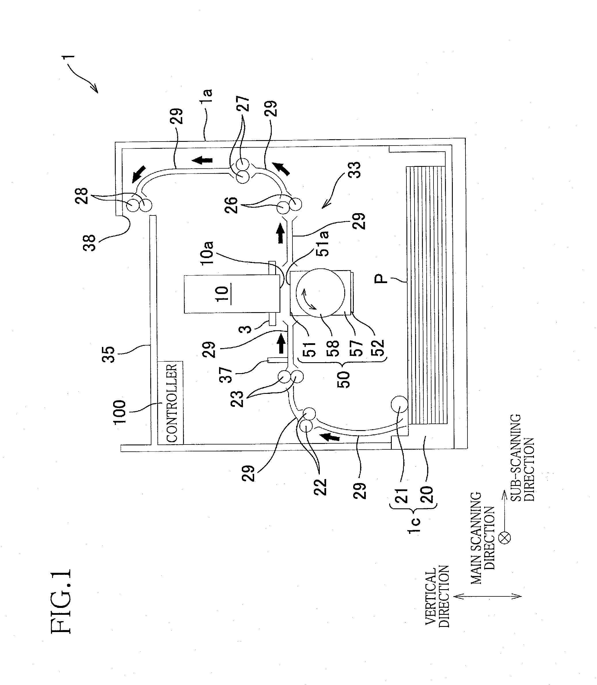
[0026]First, there will be explained an overall construction of an ink-jet printer 1 as a first embodiment with reference to FIG. 1.

[0027]The printer 1 includes a housing 1a having a rectangular parallelepiped shape. A sheet-discharge portion 35 is provided on a top plate of the housing 1a. In a space defined by the housing 1a, there is formed a sheet conveyance path through which a sheet P (as one example of a recording medium) is conveyed from a sheet-supply unit 1c which will be described below toward the sheet-discharge portion 35 along bold arrows in FIG. 1.

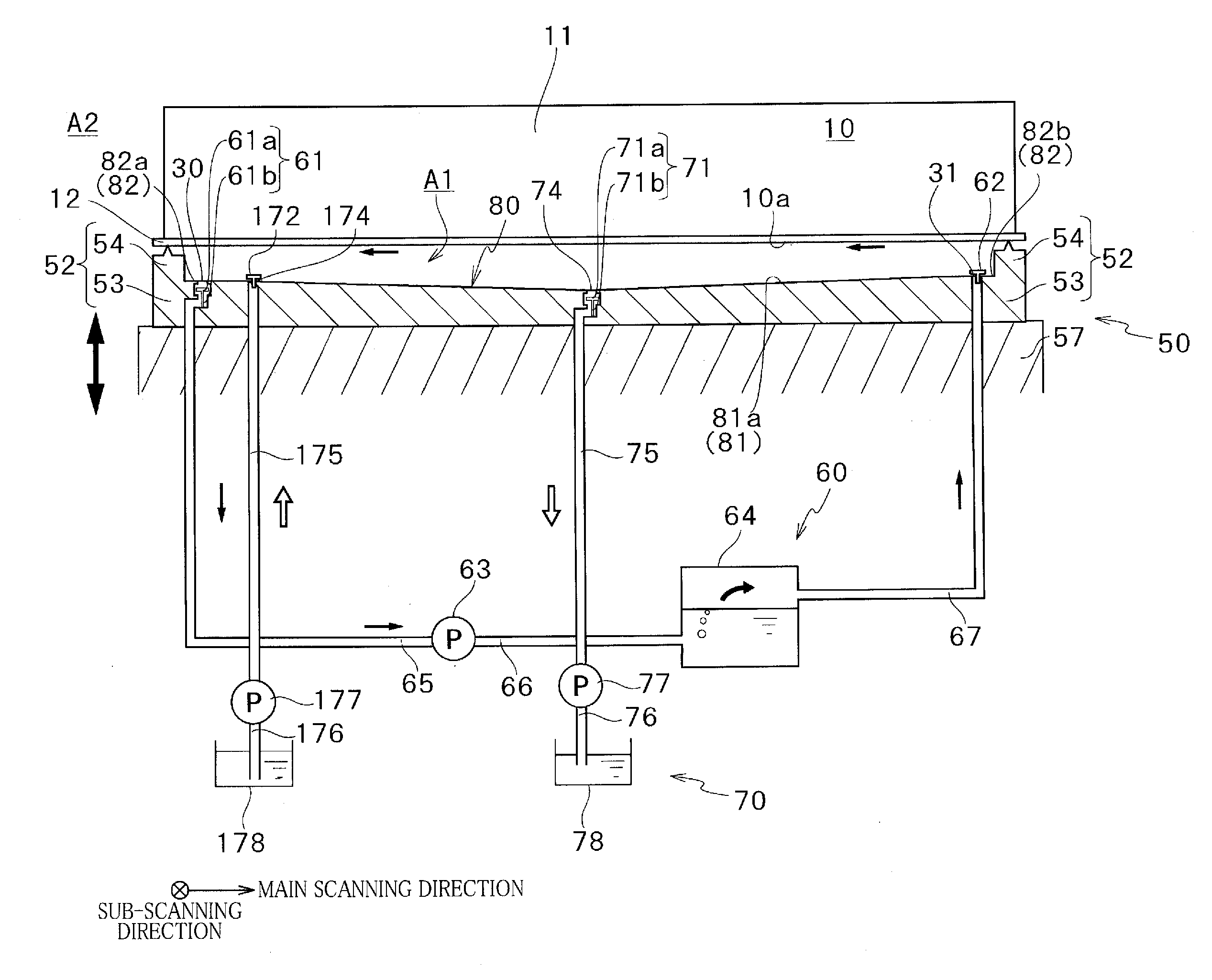
[0028]The housing 1a accommodates (a) a liquid ejection head in the form of a head 10, (b) a conveyor mechanism 33 configured to convey the sheet P through a position facing or just under an ejection face 10a of the head 10, (c) a support-cap unit 50 corresponding to the head 10, (d) a humidification unit 60 (see FIG. 5) used for a humidifying maintenance, (e) a liquid suction unit 70 (see FIG. 5) used for a liquid removal m...

second embodiment

[0097]There will be next explained a printer as a second embodiment of the present invention with reference to FIG. 9. This second embodiment is different from the first embodiment in that preventive plates 59 are provided on the facing member 53 such that the ejection area 81 is interposed therebetween in the main scanning direction. In this second embodiment, the liquid suction unit 70 does not include the cleaning liquid supplier (the cleaning-liquid tubes 175, 176, the supply pump 177, and the cleaning-liquid tank 178). Further, in this second embodiment, the wiper 9 wipes the head 10 in the liquid removal maintenance so as to remove the ink contacting the head 10 at the area facing or contacting the ejection space A1. That is, in this second embodiment, the wiper 9 and the liquid suction unit 70 are one example of the cleaner, and the mode change section 131, the capping control section 135, the air-supply-pump control section 136, the cleaning control section 138, and the wipi...

third embodiment

[0103]There will be next explained a printer as a third embodiment of the present invention with reference to FIGS. 10-12. This third embodiment is different from the first embodiment in the sealing mechanism and the capping control section 135. Specifically, in the first embodiment, the capping control section 135 controls the recessed member 52 as the sealing mechanism to move upward and downward so as to selectively establish one of the sealing state and the open state, but in this third embodiment, the sealing mechanism selectively establishes one of the sealing state and the open state by upward and downward movement of an annular movable member 502 of a cap 500 provided on the head holder 3. Further, the air outlet opening 30 and the air introduction opening 31 are formed in the facing member 53 in the first embodiment but are formed in the cap 500 provided on the head holder 3 in this third embodiment.

[0104]Further, in the first embodiment, the cleaner is the liquid suction u...


PUM


Abstract

A liquid ejection apparatus, including: a head having an ejection face having at least one ejection opening for ejecting liquid; a sealing mechanism configured to selectively establish one of a sealing state in which the sealing mechanism seals an ejection space and an open state in which the sealing mechanism does not seal the ejection space; an air introduction opening configured to open in an area that faces the ejection space in the sealing state; a humid air supplier configured to supply a humid air from the air introduction opening to the ejection space in the sealing state; a cleaner configured to clean the liquid contacting at least a part of an area of the head and the sealing mechanism, the area facing the ejection space; and a controller configured to control the cleaner to clean the liquid before the supply of the humid air supplier.

Description

CROSS REFERENCE TO RELATED APPLICATION[0001]The present application claims priority from Japanese Patent Application No. 2011-151787, which was filed on Jul. 8, 2011, the disclosure of which is herein incorporated by reference in its entirety.BACKGROUND OF THE INVENTION[0002]1. Field of the Invention[0003]The present invention relates to a liquid ejection apparatus for ejecting liquid such as ink and a humid-air supply method for the liquid ejection apparatus.[0004]2. Description of the Related Art[0005]A liquid ejection apparatus includes a head having an ejection face that has ejection openings through which liquid such as ink is ejected. If the liquid is not ejected from the ejection openings for a long time, a viscosity of the liquid near the ejection openings increases due to its vaporization, which may cause clogging of the ejection openings. The following technique is known as a technique for suppressing the clogging of the ejection openings, for example.[0006]In this techniq...

Claims


Application Information

Patent Timeline
Patent Type & Authority Applications(United States)
IPC IPC(8): B41J2/165
CPCB41J2/165B41J2/16588B41J2/16532B41J2/16505
Inventor TAIRA, HIROSHI
Owner BROTHER KOGYO KK
Why Eureka
Try Eureka