
Pixel electrode structure

Inactive Publication Date: 2013-01-10
TCL CHINA STAR OPTOELECTRONICS TECH CO LTD
View PDF3 Cites 12 Cited by
  • Summary
  • Abstract
  • Description
  • Claims
  • Application Information

AI Technical Summary

Benefits of technology

The present invention is about improving the pixel electrode structure in display devices. By designing bending branch portions with smooth curves or wavy structures, and angles between the bending branch portions and the horizontal trunk portion, the invention aims to improve transmittance and avoid color shifting defects. The bending branch portions are composed of multiple branch sections, each with a different angle to the horizontal trunk portion. This unique design leads to smoother and more uniform images, providing better quality display.

Problems solved by technology

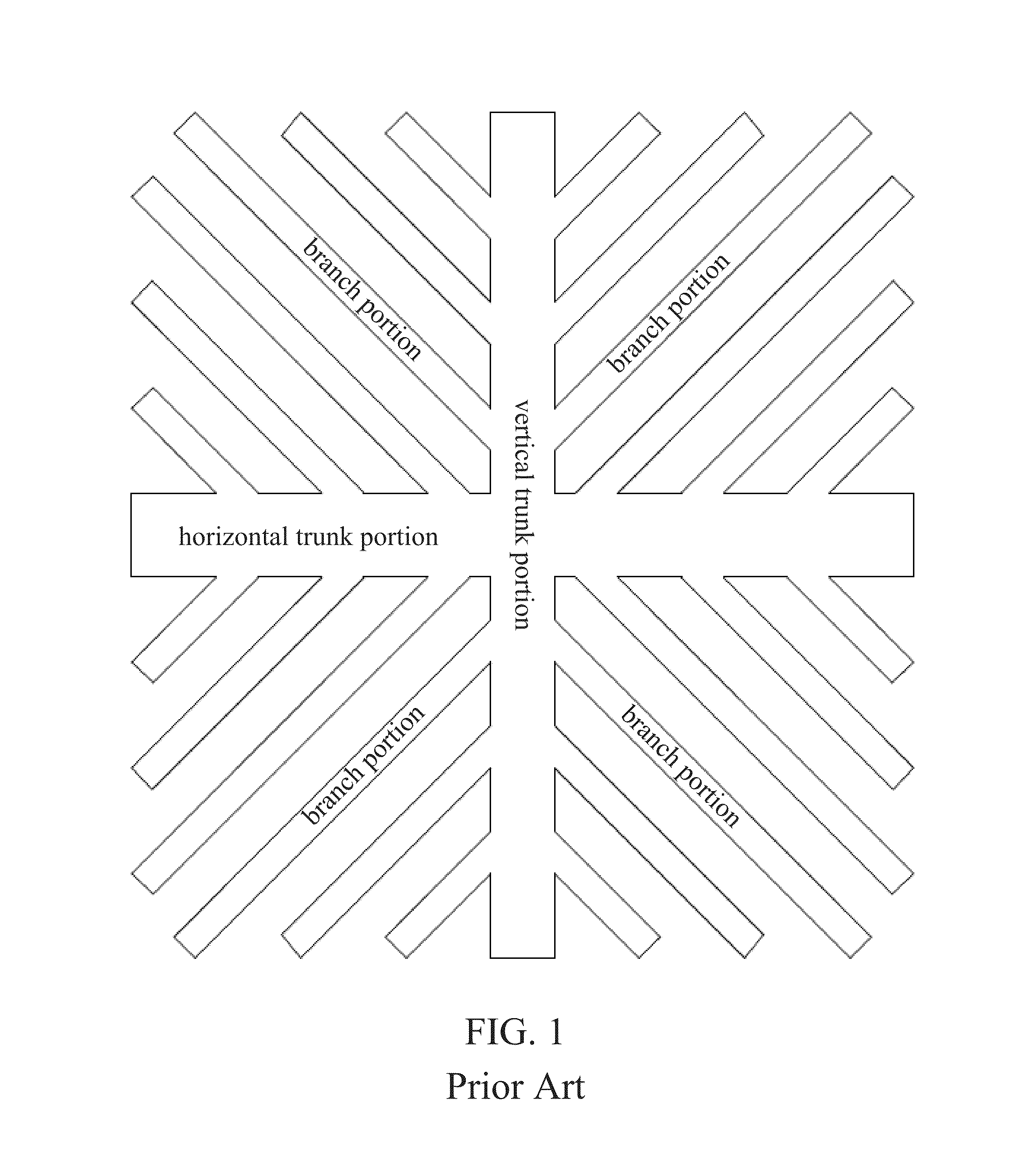
However, in the conventional “” shaped pixel electrode structure, the angles between the branch portions and the horizontal trunk portion (or the vertical trunk portion) are identical, and there are some color shifting defects existing therein, hence deteriorating a transmittance of the panel.

Method used


Image

  • Pixel electrode structure
  • Pixel electrode structure
  • Pixel electrode structure

Examples


first embodiment

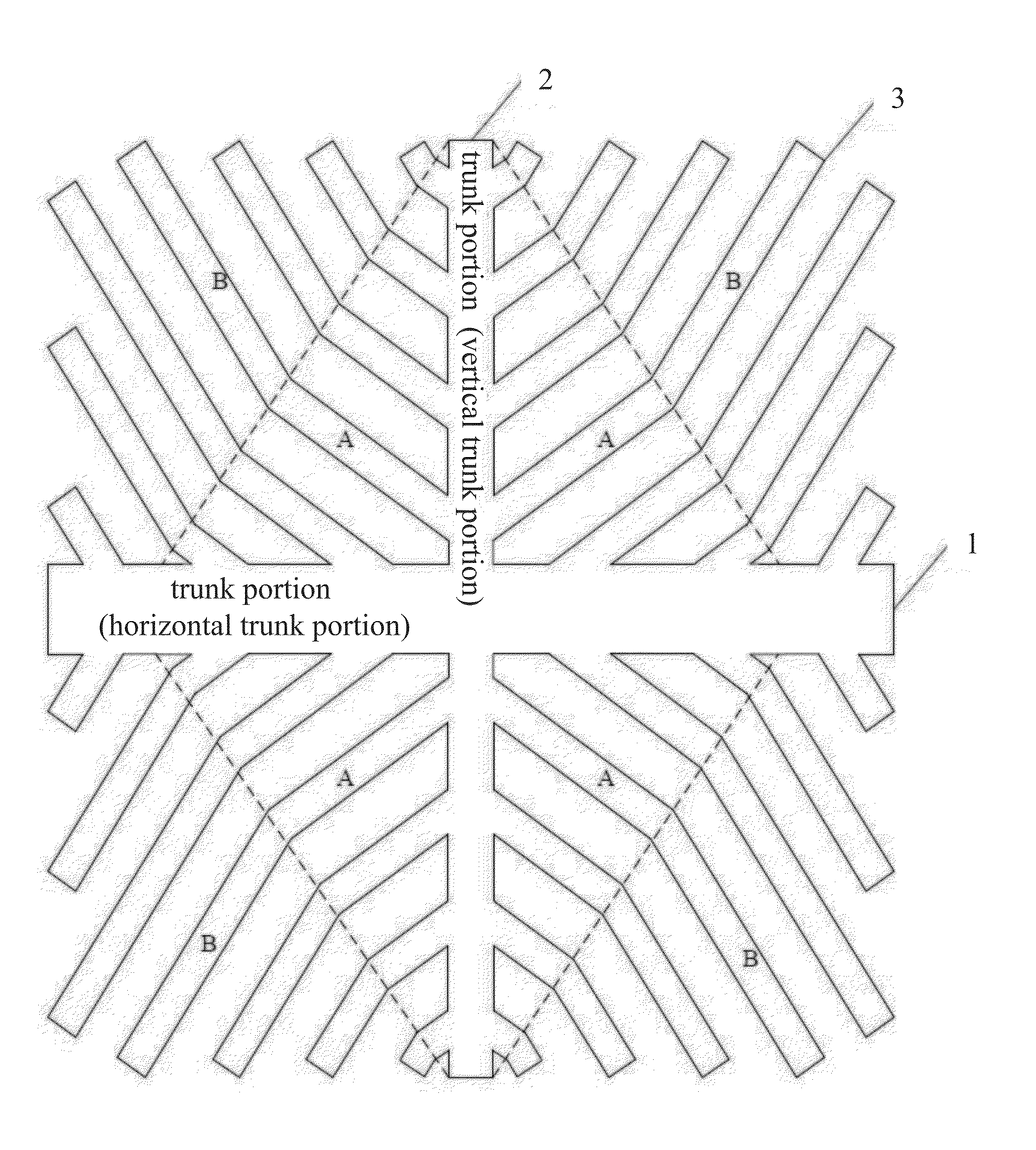
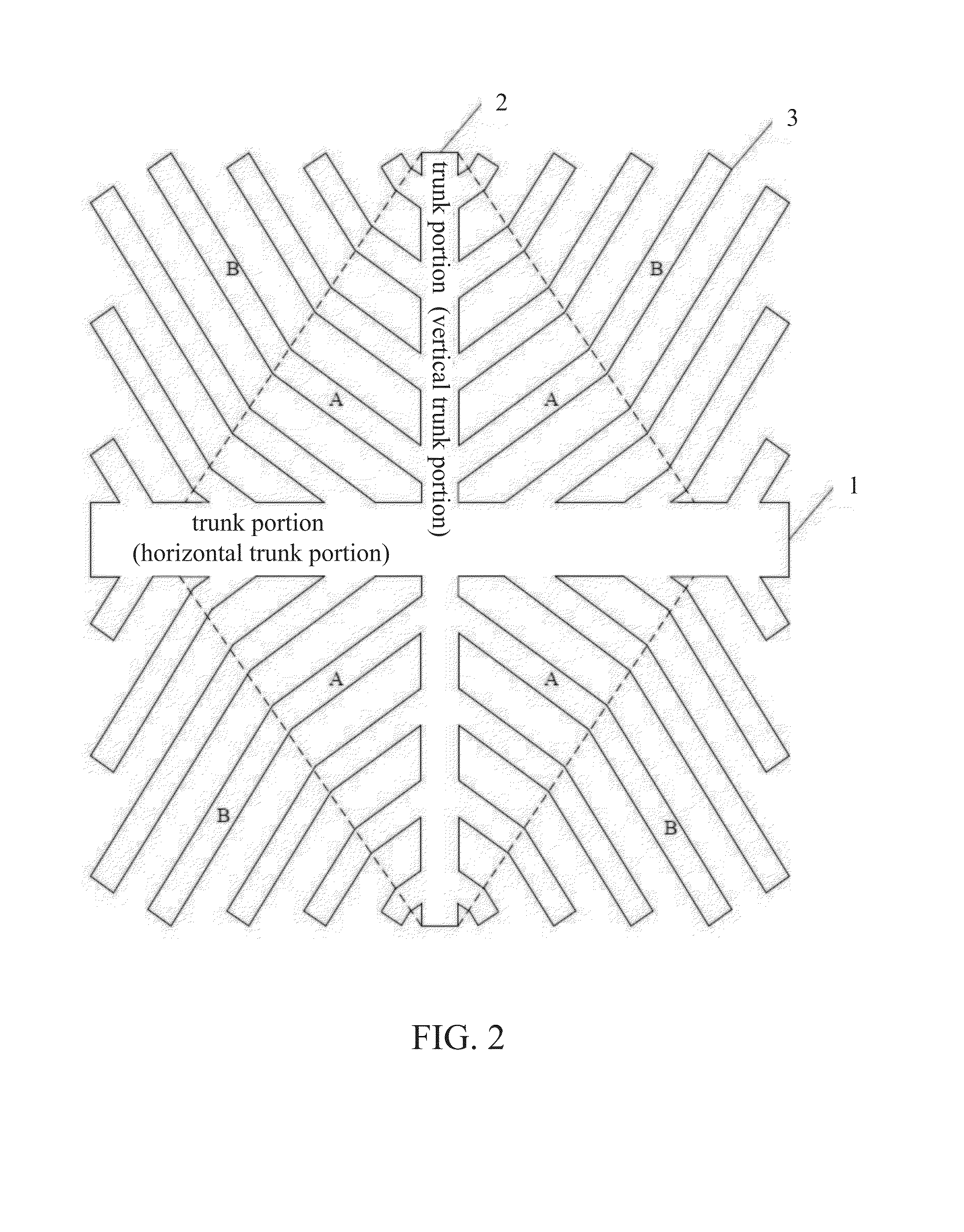
[0030]Referring to FIG. 2, FIG. 2 is a structural diagram showing the pixel electrode structure according to the present invention.

[0031]The pixel electrode structure of this embodiment comprises a trunk portion and a plurality of branch portions. The trunk portion includes a horizontal trunk portion 1 and a vertical trunk portion 2. The horizontal trunk portion 1 and the vertical trunk portion 2 are intersected vertically at the center thereof to form a “” shaped structure. The pixel electrode structure is divided into the four sub-pixel regions by the “” shaped structure, and the electrodes disposed in the four sub-pixel regions are called the branch portions. The branch portions in each sub-pixel region includes a plurality of the bending branch portions 3, and each of the bending branch portions 3 is connected to the trunk portion, and there are the slits between the bending branch portions 3.

[0032]In this embodiment, each of the bending branch portions 3 has two angle designs. ...

second embodiment

[0033]Referring to FIG. 3, FIG. 3 is a structural diagram showing the pixel electrode structure according to the present invention.

[0034]In this embodiment, each of the bending branch portions 3 has two angle designs. Specifically, as shown in FIG. 3, the bending branch portions 3 are composed of branch sections A and B. The angle between the branch sections A and the horizontal trunk portion 1 is different to the angle between the branch sections B and the horizontal trunk portion 1, and the angle between the branch sections A and the horizontal trunk portion 1 is larger than the angle between the branch sections B and the horizontal trunk portion 1, so as to allow the bending branch portions 3 to have the bending structures.

[0035]The pixel electrode structures provide by the first embodiment and the second embodiment comprises the bending structures of the bending branch portions which are composes of the two branch sections, and the angles between the two branch sections and the ...

third embodiment

[0036]Referring to FIG. 4, FIG. 4 is a structural diagram showing the pixel electrode structure according to the present invention.

[0037]In the pixel electrode structure of this embodiment of the present invention, the angles between the branch sections of the bending branch portions 3 and the horizontal trunk portion 1 are gradually increased from the branch section, which is closest to an intersected center of the horizontal trunk portion 1 and the vertical trunk portion 2, to the farthest branch section away the intersected center thereof.

[0038]Specifically, as shown in FIG. 4, the pixel electrode structure comprises the trunk portion and the plurality of branch portions. The trunk portion includes the horizontal trunk portion 1 and the vertical trunk portion 2. The horizontal trunk portion 1 and the vertical trunk portion 2 are intersected vertically at the center thereof to form a “” shaped structure. The pixel electrode structure is divided into the four sub-pixel regions by t...


PUM

PropertyMeasurementUnit
Angleaaaaaaaaaa
Angleaaaaaaaaaa
Angleaaaaaaaaaa

Abstract

The present invention provides a pixel electrode structure comprising: a trunk portion including a vertical trunk portion and a horizontal trunk portion which are intersected vertically; and branch portions disposed in four sub-pixel regions which are divided by the vertical trunk portion and the horizontal trunk portion, wherein the branch portions in each of the sub-pixel regions include bending branch portions, and each of the bending branch portions is composed of branch sections, and angles between each adjacent two of the branch sections and the horizontal trunk portion are different, and there are slits between the bending branch portions. The present invention can efficiently solve the problems of a color shifting defect and a low color shifting defects resulting from the constant angle between the branch portions and the horizontal trunk portion or the vertical trunk portion.

Description

FIELD OF THE INVENTION[0001]The present invention relates to a field of a liquid crystal display (LCD) technology, and more particularly to a pixel electrode structure of an LCD apparatus.BACKGROUND OF THE INVENTION[0002]LCD is one of popular flat displays. The LCD comprises substrates having electrodes for generating an electric field, such as pixel electrodes and common electrodes, and a liquid crystal (LC) layer disposed between the substrates. When a voltage is applied to the electrodes to generating the electric field across the LC layer, an orientation of LC molecules of the LC layer is determined by the electric field, thereby adjusting a polarization of a light emitted to the LC layer, allowing the LCD to display images.[0003]At present, a technique called polymer stabilized vertical alignment (PSVA) has been developed. In this technique, monomers of a proper concentration are mixed a LC material, and the mixed LC material is uniformly oscillated. Subsequently, the mixed LC ...

Claims


Application Information

Patent Timeline
IPC IPC(8): G02F1/1343
CPCG02F1/133707G02F2001/13775G02F1/1393G02F1/134336G02F1/13775
Inventor KANG, CHIH-TSUNG
Owner TCL CHINA STAR OPTOELECTRONICS TECH CO LTD
Learn More