
Lighting assembly for vehicle

a technology for vehicle lighting and assembly, applied in the direction of lighting support devices, lighting and heating apparatus, transportation and packaging, etc., can solve the problems of only getting a well-defined beam, moving parts such as motors or actuators that physically swivel the moveable parts of the headlamp arrangement, and largely unavoidable effects, etc., to achieve simple and economical lighting assembly design.

Active Publication Date: 2013-01-10
LUMILEDS
View PDF11 Cites 20 Cited by
  • Summary
  • Abstract
  • Description
  • Claims
  • Application Information

AI Technical Summary

Benefits of technology

The invention is a lighting assembly for vehicles that uses a special projection lens to create a high-quality beam with improved visibility and reduced glare. The asymmetry displacement of the optical axis ensures that all light is used for all degrees of beam swivel, and a high-quality beam can be obtained for all front beam requirements. The lighting assembly requires no moving parts and is particularly useful for vehicles with only a single headlamp. The asymmetry displacement of the optical axis can be adjusted to direct the front beam towards a critical region and optimize illumination. Overall, the invention allows for a simple and economical lighting assembly design while achieving improved lighting performance.

Problems solved by technology

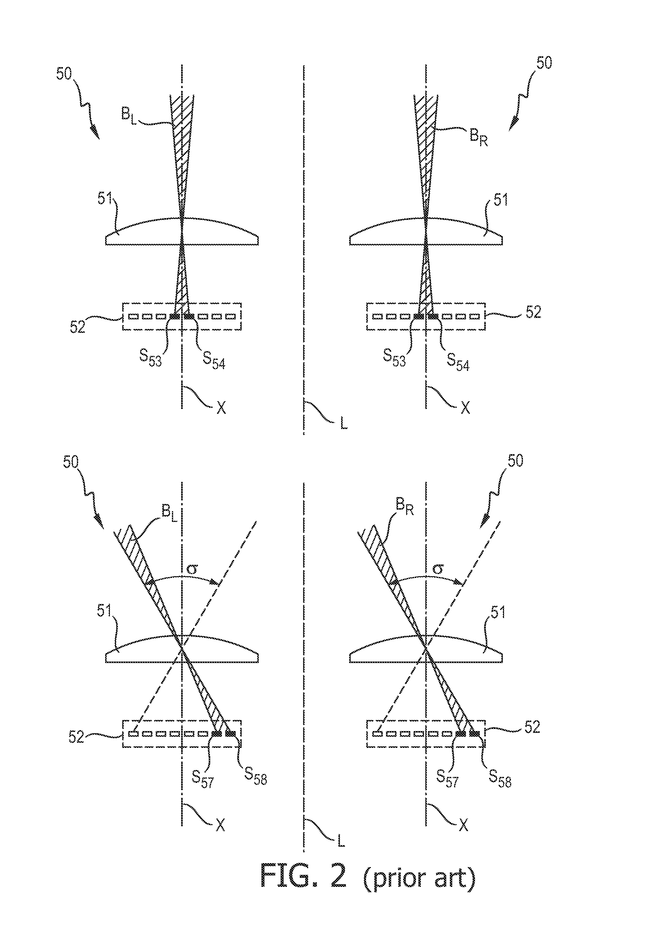
This effect is largely unavoidable in conventional arrangements since, for various reasons, the body of the headlamp cannot extend beyond the body of the vehicle, and the projection lens is positioned inside the headlamp (behind the front glass cover).
Secondly, any moving parts such as motors or actuators required to physically swivel the moveable parts of the headlamp arrangements are vulnerable to damage or failure.
However, a well-defined beam can only be obtained using the LEDs close to the optical axis.
The light originating from the light sources further away from the optical axis, namely those light sources used to generate the extreme swiveled beam, is subject to aberration, and the resulting beam is poorly defined.
To obtain a well-defined beam in keeping with ECE and SAE regulations, therefore, the projection lens must be designed to compensate for this aberration, but such lens design generally presents a high cost factor.

Method used


Image

  • Lighting assembly for vehicle
  • Lighting assembly for vehicle
  • Lighting assembly for vehicle

Examples


Embodiment Construction

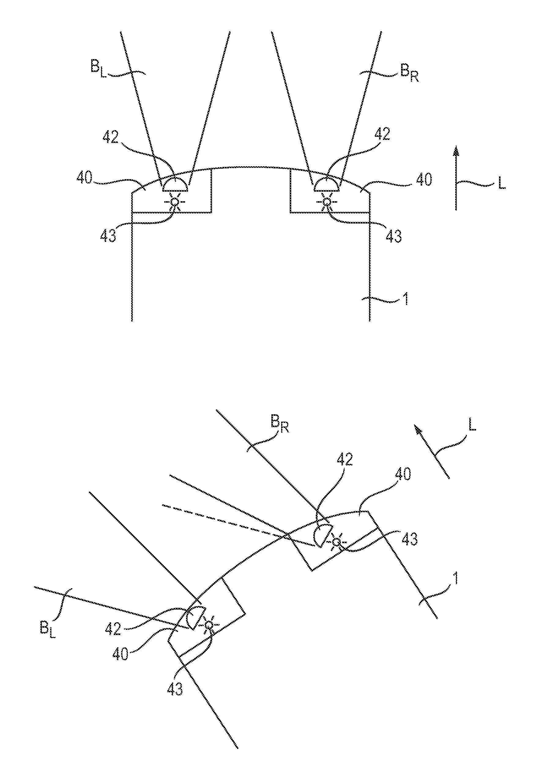
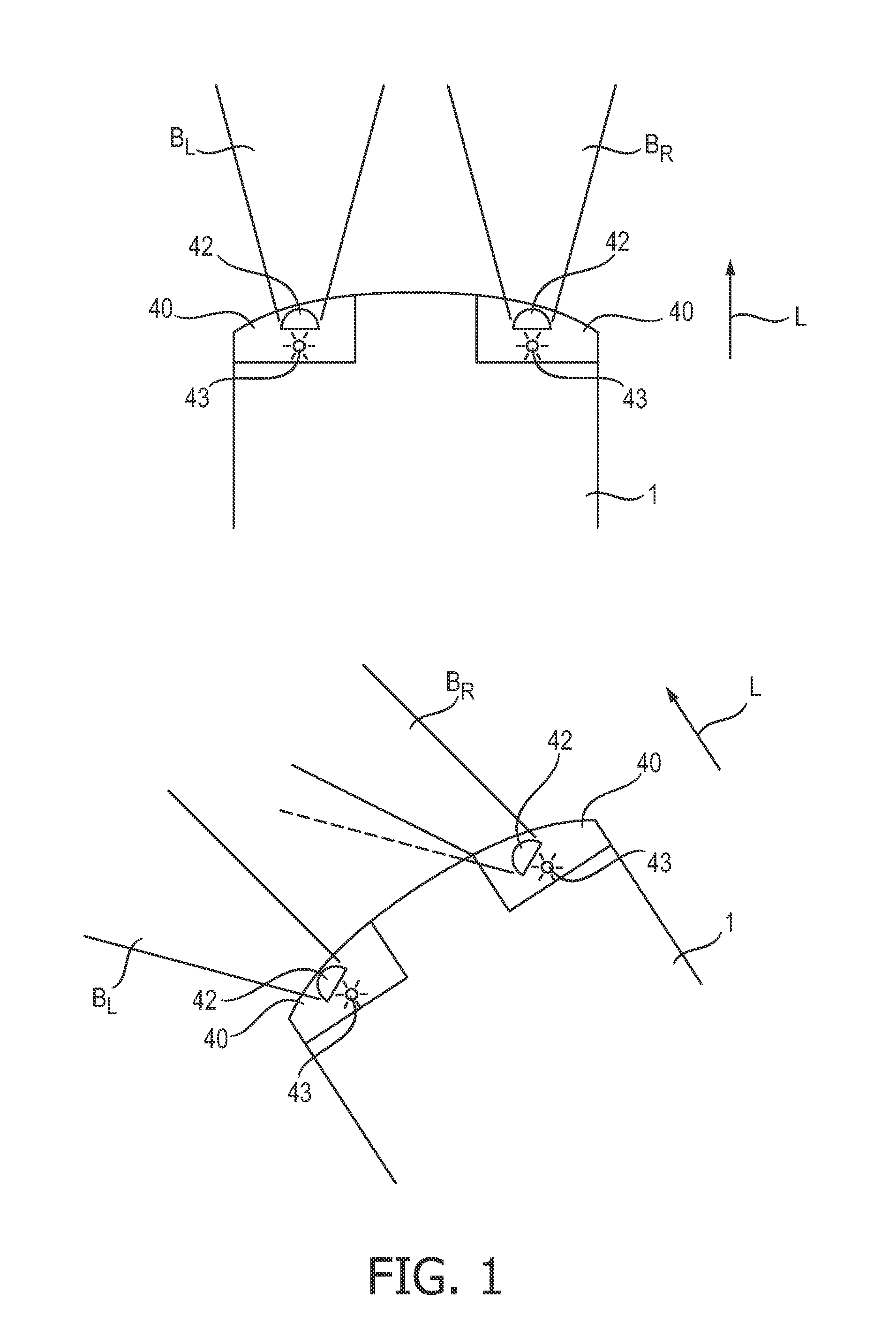
[0033]FIG. 1 shows a simplified plan view of a vehicle 1 with a prior art lighting arrangement comprising left and right headlamps 40, each with an AFL front lighting assembly 40, for generating a front beam BL, BR, which front beam BL, BR comprises a left beam BL and a right beam BR. Each AFL front lighting assembly 40 comprises a projection lens 42 in front of a point light source 43, such as a xenon or halogen lamp 43. In the top of the diagram, the vehicle 1 is shown driving straight ahead, so that the front beam BL, BR is directed essentially parallel to a longitudinal axis L of the vehicle 1. The complete headlamp 40, comprising the projection lens 42 and the light source 43, can be mechanically swiveled to control the direction of projection of the front beam BL, BR. In the bottom part of the diagram, the vehicle 1 is turning to the left, and the front beam BL, BR is also directed or swiveled to the left. As the diagram shows, the lighting assemblies 40 are swiveled in order ...


PUM


Abstract

The invention describes a lighting assembly (10, 10′, 20, 20′) for use in a lighting arrangement (2) of a vehicle (1), comprising a projection lens (11, 21) and an array (12, 22) of light sources (S11, . . . , S26), wherein the projection lens (11, 21) and the light source array (12, 22) are arranged according to an asymmetry displacement (Φi, Φ2, di, d2) of the optical axis (X1, X2) of the projection lens (11, 21), and wherein the light sources (S11, . . . , S26) of the light source array (12, 22) of the lighting assembly (10, 10′, 20, 20′) are individually controllable to adjust a swivel angle (σ1, σ2) of a light beam (BL, BH) generated by that lighting assembly (10, 10′, 20, 20′). The invention further describes a controller (3) for controlling the light sources (S11, . . . , S26) of such a lighting assembly (10, 10′, 20, 20′). The invention also describes a lighting arrangement (2) for a vehicle (1), comprising such a lighting assembly (10, 10′, 20, 20′) and such a controller (3) for controlling the light sources (S11, . . . , S26) of the lighting assembly (10, 10′, 20, 20′) to adjust the swivel angle (σ1 σ2) of the light beam (BL, BR). The invention also describes a method of generating a front beam (BL, BR) for a vehicle (1) comprising such a lighting assembly (10, 10′, 20, 20′).

Description

FIELD OF THE INVENTION[0001]The invention describes a lighting assembly, a controller for such a lighting assembly, an automotive headlamp comprising such a lighting assembly, and a method of generating a front beam for a vehicle comprising such a lighting assembly.BACKGROUND OF THE INVENTION[0002]Adaptive Front Lighting is being offered by several automotive manufacturers. In AFL, the vehicle's left and right headlamps are controlled together to adapt or adjust the front beams to the momentary driving situation. For example, when turning to the left or right, a controller determines the angle of turning and causes a part of the headlamp—usually the projection lens—to swivel by a corresponding swivel angle, so that the beam also swivels. In this way, the low beam does not remain stationary relative to the vehicle as is the case for conventional headlamps, but it is directed deliberately ‘into’ the turn.[0003]While such swiveling headlamps offer the advantage of being able to activel...

Claims


Application Information

Patent Timeline
IPC IPC(8): B60Q1/12
CPCB60Q1/122F21S48/1747F21S48/1154F21S41/143F21S41/663F21S41/153F21W2102/19
Inventor SIKKENS, MARTENDE JONG, MARCELBOOIJ, SILVIA MARIACREUSEN, MARTINUS PETRUS
Owner LUMILEDS
Learn More