
Card Connector

Inactive Publication Date: 2013-01-10
MOLEX INC
View PDF5 Cites 16 Cited by
  • Summary
  • Abstract
  • Description
  • Claims
  • Application Information

AI Technical Summary

Benefits of technology

The present patent aims to provide a highly reliable card connector that can prevent mistaken deep insertion of a card and allow for easy removal of a mistakenly inserted card. The card connector has a simple constitution, including a convex part with an inclined part that prevents mistaken insertion. The front end of the card has an inclined part that matches the inclined part of the connector. Additionally, the tip end of the front end holding part makes contact outside the inclined part. The housing has an insertion opening convex part formed in the slide member side and a cover member with a side plate part that contacts the side edge of an incorrect card and controls the inclination of the incorrect card in the transverse direction. Overall, the present patent results in increased reliability and prevents mistaken deep insertion of a card.

Problems solved by technology

Therefore, the cards may sometimes be inserted incorrectly.
In addition, when the cards are so inserted, since parts other than the pads on the outsides of the cards touch the connecting terminals of the card connector, these terminals can be bent or broken.
However, in the conventional card connector, when a card of a kind which the card connector is made to be used with—that is, a card of the correct kind—is inserted in an incorrect fashion, the insertion of the card can be prevented, but when a card of a kind for which the card connector is not made, that is an incorrect kind, and one which is smaller than the correct kind of card, is inserted, the insertion of the card cannot be prevented.
Therefore, users may try to insert different kinds of cards into the card connector, mistaking them from the correct kind In particular, if a different kind of card has the same length as the correct kind of card but a smaller width than the correct one, it will not touch the front end of the elastic deforming part 826; therefore, insertion of it into the card connector cannot be prevented.
Moreover, if it has been inserted deeply into the card connector, the position of the card is not stable; therefore, the card may be caught in the housing in such a way that it cannot be extracted.

Method used


Image

  • Card Connector
  • Card Connector
  • Card Connector

Examples


Embodiment Construction

[0025]While the Present Disclosure may be susceptible to embodiment in different forms, there is shown in the Figures, and will be described herein in detail, specific embodiments, with the understanding that the Present Disclosure is to be considered an exemplification of the principles of the Present Disclosure, and is not intended to limit the Present Disclosure to that as illustrated.

[0026]As such, references to a feature or aspect are intended to describe a feature or aspect of an example of the Present Disclosure, not to imply that every embodiment thereof must have the described feature or aspect. Furthermore, it should be noted that the description illustrates a number of features. While certain features have been combined together to illustrate potential system designs, those features may also be used in other combinations not expressly disclosed. Thus, the depicted combinations are not intended to be limiting, unless otherwise noted.

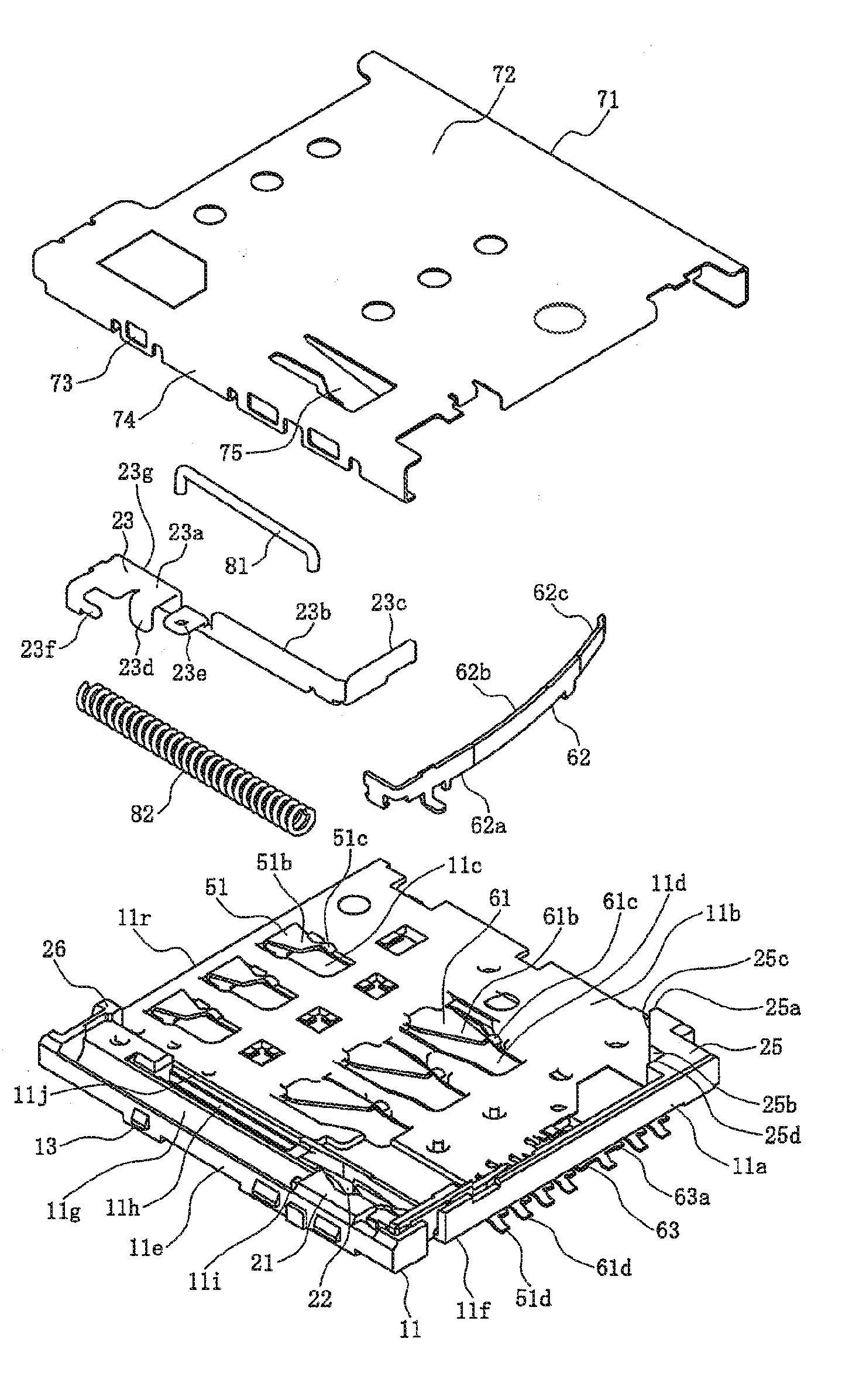
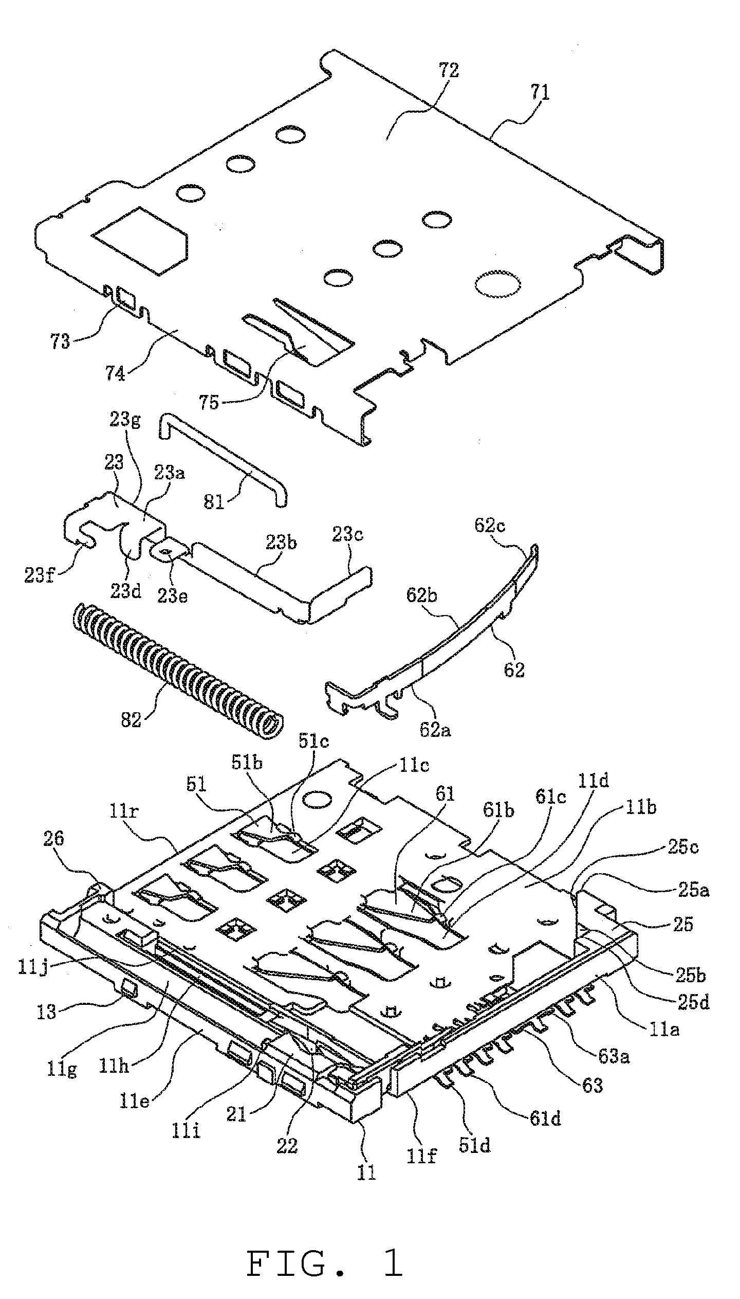
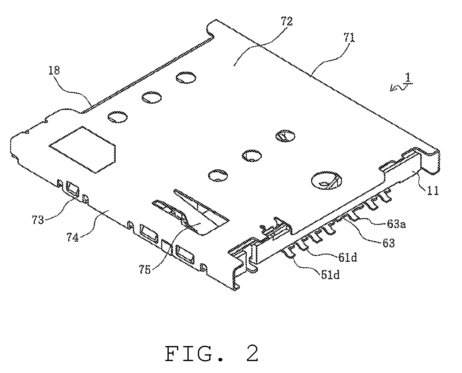
[0027]In the embodiments illustrated in ...


PUM


Abstract

A slide member includes a side edge holding part, which extends towards the front end edge of the housing, and a front end holding part, which is connected to the front end of the side edge holding part and extends in the transverse direction of the housing. The slide member is able to slide forward and backward along one side edge of the bottom wall part of the housing. The housing contains a mistaken insertion prevention convex part which the front end or rear end of a mistakenly inserted card contacts.

Description

REFERENCE To RELATED APPLICATIONS[0001]The Present Disclosure claims priority to prior-filed Japanese Patent Application No. 2011-149635, entitled “Card Connector,” filed on 6 Jul. 2011 with the Japanese Patent Office. The content of the aforementioned Patent Application is incorporated in its entirety herein.BACKGROUND OF THE PRESENT DISCLOSURE[0002]The Present Disclosure relates, generally, to a card connector, and, more particularly, to a card connector which can prevent the mistaken insertion of a card, and allow a card which has been mistakenly inserted to be removed.[0003]Traditionally, card connectors have been provided in electronic devices in order to use memory cards. In recent years, with the rapid miniaturization of electronic devices, both memory cards and card connectors have shown a tendency toward miniaturization as well. Moreover, card connectors are frequently disposed in locations which are comparatively hard to see (i.e., on the sides, backs, etc. of the devices,...

Claims


Application Information

Patent Timeline
IPC IPC(8): H01R24/00
CPCG06K13/0825
Inventor UESAKA, RYOTAKASAKI, MASAMITSUNAITO, YUJITOMITA, MITSUHIRO
Owner MOLEX INC
Features
  • Generate Ideas
  • Intellectual Property
  • Life Sciences
  • Materials
  • Tech Scout
  • Unparalleled Data Quality
  • Higher Quality Content
  • 60% Fewer Hallucinations
Learn More